


Tutorials: Volume Generation
The final step towards a finished grid is to generate an outer boundary, assign boundary conditions, and generate the volume grid. The outer boundary is really dependent on the geometry and the problem being solved. For example, the outer boundary for a supersonic case can be much closer than for a subsonic case. For illustration, the outer boundary will be 15 body lengths away in all directions. To start, download the file flying_minnow_clean_split_spaced.igs.gz or continue from the last tutorial.
1. Read the file
flying_minnow_clean_split_spaced.igs.gz
in with gluing and trimming enabled. Select the two points shown and  to get an approximate body length. The message window reports almost
25.5 units long. Click
to get an approximate body length. The message window reports almost
25.5 units long. Click  to get an approximate center.
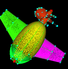
2. Leaving the point created selected, enter 255 (10x25.5) in
the  field. Leave the start and end angles at the default (0 and 90 respectively).
Click
field. Leave the start and end angles at the default (0 and 90 respectively).
Click  .
Select the curve and point shown and go to the
.
Select the curve and point shown and go to the
 Application. Since the rotation is about the
x-axis, there is no need to select a vector. Make sure the VX in
Application. Since the rotation is about the
x-axis, there is no need to select a vector. Make sure the VX in  is selected. Leave the
  field at 0.0 but change the
 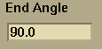 to 90.0 and click
 .
.
 and
and
 .
.
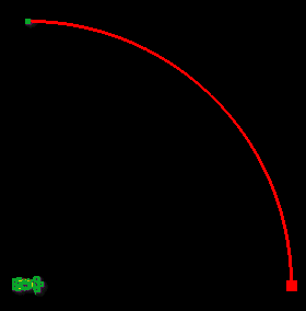
3. Select the surface and point shown and go the
 Application.
Change the
Application.
Change the 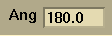 to 90.0. Change
  to 3. Make sure the VX in vectors component field
is clicked to rotate about the x-axis. Click
to 3. Make sure the VX in vectors component field
is clicked to rotate about the x-axis. Click  .
.
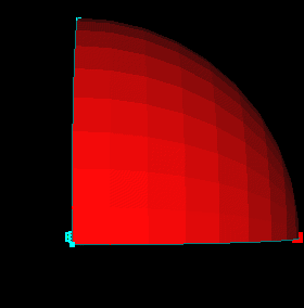
4. Select the surfaces shown and the point shown. Change
the (VX,VY,VZ) fields in the Vector application
to (1,0,0). Click  .
Select the surfaces of the sphere just created, enter "OuterBoundary"
in the name field of the group editor
area and
.
Select the surfaces of the sphere just created, enter "OuterBoundary"
in the name field of the group editor
area and  . Check the topology and glue the edges of the newly created surfaces.
Click
. Check the topology and glue the edges of the newly created surfaces.
Click  to glue the edges and then click
  to ensure that the model is topologically valid.
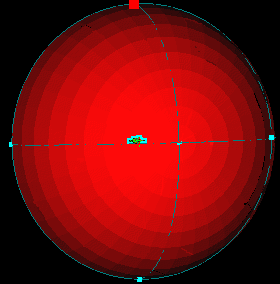
5. Select the 6 outer boundary points. Go to the
 application and
enter a value of 30 for the spacing,
application and
enter a value of 30 for the spacing,  ,
and
,
and  .
.
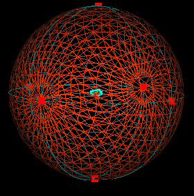
6. In the  application,
set the Absolute Initial Spacing to 2.5e-4. Click the
Prop, Body, LeftWing, RightWing, and Mouth groups. Select
application,
set the Absolute Initial Spacing to 2.5e-4. Click the
Prop, Body, LeftWing, RightWing, and Mouth groups. Select
 and
and  and
and  .
Click the OuterBoundary group. Select
and .
Generate the volume grid by clicking
.
Click the OuterBoundary group. Select
and .
Generate the volume grid by clicking  .
(This could take a while. If possible change the host
field to another machine). For illustration, set only normal
growth on groups Prop, Body, LeftWing, RightWing, and Mouth and generate
the volume grid again. (Change the case name in fileio so your previous
volume grid doesn't get written over.) This disables reconnection
on the surface grid. In this case, the volume grid won't generate.
(It makes it part of the way and dies). In some cases, the resulting
volume grid is better than with reconnection on.
.
(This could take a while. If possible change the host
field to another machine). For illustration, set only normal
growth on groups Prop, Body, LeftWing, RightWing, and Mouth and generate
the volume grid again. (Change the case name in fileio so your previous
volume grid doesn't get written over.) This disables reconnection
on the surface grid. In this case, the volume grid won't generate.
(It makes it part of the way and dies). In some cases, the resulting
volume grid is better than with reconnection on.
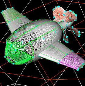
7. Read (sm -grid gridfilename) in the good grid
(the one generated with reconnection on). The group names are not
retained so find the group containing the outer boundary,  ,
and
,
and .
Make the S_grid Shaded. In the
.
Make the S_grid Shaded. In the  application, turn the preview plane on. Change to the XZ plane,
change the Y value to 0, and .
Turn the preview plane off.
application, turn the preview plane on. Change to the XZ plane,
change the Y value to 0, and .
Turn the preview plane off.
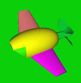
8. Left click somewhere on the prop close to the cutting plane
and zoom. You can see the viscous packing close to the solid surface.
Set the CuttingPlane to Invisible in the global
graphics edit area. At the top of the panel, select
Volume Weather Map and click  .
This gives a plot of the angles in the volume grid. Click
.
This gives a plot of the angles in the volume grid. Click  .
This returns the max and min angles to the message window.
.
This returns the max and min angles to the message window.
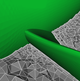
This completes the grid generation process. The various
functions in the
panel can be used for quality evaluation. Practice is the best way
to become proficient in grid generation. Good Luck!
 |
 |
 |
 |