


Volume Grid Generation

Volume Grid Generation Applications
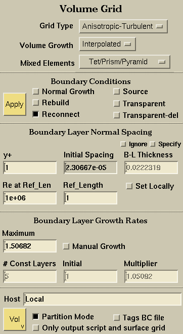
SolidMesh provides a user friendly front-end to the Advancing-Front/Local-Reconnection 3D (AFLR4) unstructured grid generator. AFLR4 is a stand-alone unstructured tetrahedral element grid generation system. AFLR4 generates a tetrahedral isotropic volume grid or a mixed element (tetrahedra, pentahedra and prisms) anisotropic boundary layer volume grid from a surface triangulation.
Global Grid Options:

The grid type selector allows the user to specify the type of volume grid:
- An Isotropic volume grid is used for Euler calculations. The volume grid point placement distances are interpolated from the surface grid.
- An Anisotropic-Laminar grid is used for Navier-Stokes viscous calculations where the boundary-layer must be resolved. An anisotropic grid needs a boundary layer spacing and growth rate in addition to the surface grid. A normal point placement technique is used to create right-angled tetrahedron, pentahedron or prism elements. The growth of the boundary-layer assumes a laminar boundary-layer velocity profile.
- An Anisotropic-Turbulent grid is similar to the Anisotropic-Laminar except the growth of the boundary-layer growth assumes a turbulent boundary-layer velocity profile.

The volume element size in the field is determined by using interpolation to smoothly propagate the point spacing within the field from the boundary surfaces. With optional growth, the element size is determined from interpolation and geometric growth normal to the boundary surfaces. There are four options available:
- Interpolated no growth specified, growth entirely determined by interpolation.
- Moderate growth normal to the surface at a geometric growth rate of 1.2.
- High growth normal to the surface at a geometric growth rate of 1.5.
- Very high growth normal to the surface at a geometric growth rate of 2.0.

Determines if a boundary-layer grid will output tetrahedra only or a mix element transition.
- Tet Tetrahedral elements only.
- Tet/Prism/Pyramid Tetrahedral, Prism, and Pyramid elements allowed.
- Tet/Prism/Pyramid/Hex Tetrahedral, Prism, Pyramid, and Hexahedral elements allowed.
Boundary Conditions:

Volume grid options may only be applied to Groups. To apply a set of boundary conditions to a group, select the group, set all of the appropriate boundary condition toggles and select the Apply button.
The normal growth toggle specifies if a group of surfaces is a viscous boundary layer. If it is, and a boundary layer type grid is specified, the volume grid generator will build an anisotropic boundary layer grid off of these surfaces. NOTE: If you have specified an anisotropic type grid, there should be at least one group specified as a viscous boundary layer.

The rebuild toggle allows surfaces in the applied group to
be rebuilt by the volume grid generator to allow the viscous boundary-layer
elements to cleanly connect and terminate. This boundary condition should be used
for planar surfaces that intersect surfaces with Normal Growth.
NOTE: The precedence
surface grid boundary condition should always be applied to symmetry plane surfaces.
The reconnection toggle specifies if a Group's surface grid can be reconnected (points stay the same but edges are swapped on the triangles) during the volume grid generation process. Reconnecting the surface is highly recommended as it allows the volume grid generator to produce higher-quality grids. The Reconnect boundary condition will not be applied if the Group contains periodic surfaces.
The source toggle specifies if a Group's surface grid is used as a source control surface in the interior of the volume grid. Each point on the surface grid is inserted in the volume grid as a point source. The boundary faces of the source surfaces are not retained in the volume grid. Individual line and point sources can also be created by placing a physical curve or vertex in a group with this boundary condition applied. The physical curve edge grid and the vertex will be used as point sources in the volume grid. Note that source points that interfere with the boundary layer will not be inserted. See the FAQ on the differences among the Source, Transparent, and Transparent-Delete boundary conditions.

The transparency toggle specifies if a group's surface grid forms a solid wall or is a transparent control surface in the interior of the volume grid. Transparent surfaces are retained in the volume grid and may impede the growth of the boundary-layer if they are in close proximity to Normal Growth surfaces. See the FAQ on the differences among the Source, Transparent, and Transparent-Delete boundary conditions. Normal growth is allowed on Transparent surfaces and they may intersect a normal growth boundary layer surface. This may be particularly useful for refinement in wake regions.

Similar to the Transparent boundary condition, except that the transparent surface is not retained in the volume grid. Only the specification of the surface in the boundary surface face connectivity is removed. The nodes remain part of the final interior volume grid. See the FAQ on the differences among the Source, Transparent, and Transparent-Delete boundary conditions. Normal growth is allowed on Transparent-Delete surfaces and they may intersect a normal growth boundary layer surface. This may be particularly useful for refinement in wake regions.
Isotropic Variables

Specify the maximum element size in the field. The element size in the field is determined using either interpolation or growth normal to the boundary surfaces.
- None The maximum element size is not limited by the maximum allowable distribution function (default).
- From Bndry The maximum element size is limited to be less than the maximum point spacing for the boundary surface grid.
- Specify Specify the maximum allowable distribution function and use it to limit the maximum element size.
Anisotropic Variables: Boundary-Layer Spacing
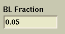
Specify the fraction of laminar boundary-layer thickness to use in determining the initial spacing normal to boundary-layer surfaces. When the BL fraction value is changed, the Boundary-Layer Fraction text field becomes active and the Initial Normal Spacing field becomes inactive (grayed background). The corresponding Initial Normal Spacing is computed using the specified Reynolds Number and Reference Length
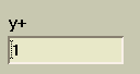
Specify the y+ for a turbulent boundary-layer to use in determining the initial spacing normal to boundary-layer surfaces. When the y+ value is changed, the y+ text field becomes active and the Initial Normal Spacing field becomes inactive (grayed background). The corresponding Initial Normal Spacing is computed using the specified Reynolds Number and Reference Length.
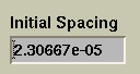
Specify the initial normal spacing normal to the boundary-layer surfaces. When the value of the initial normal spacing is changed, the Initial Normal Spacing text field becomes active and y+ (or BL Fraction) field becomes inactive. The corresponding y+ is computed using the specified Reynolds Number and Reference Length.
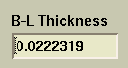
Specify the boundary-layer thickness for boundary-layer surfaces. If both the Specify and Ignore toggles are not set, a value based on either a laminar or turbulent velocity profile will be calucated using the specified Reynolds Number and Reference Length.

If the Ignore toggle is selected, the boundary-layer thickness (either specified or calculated from a laminar or turbulent profile) is ignored. In this case, the boundary-layer normal generation will attempt to continue until the normal spacing is close to the nearby isotropic value. This is particularly useful for constructing grids used in internal flow applications. If both the Specify and Ignore toggles are not set, a value based on either a laminar or turblent velocity profile will be calculated automatically.

Specify the boundary-layer thickness. If the BL thickness is specified, the boundary-layer normal generation will attempt to continue beyond that thickness. If both the Specify and Ignore toggles are not set, a value based on either a laminar or turbulent velocity profile will be calculated automatically.
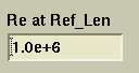
Specify the reference Reynolds number to use in determining the parameters that control spacing normal to boundary-layer surfaces. The value of the Reynolds number specified is the Reynolds number at the Reference Length. When the value of the Reynolds number is changed, either the value of y+ or Initial Spacing is updated, depending on which is active.
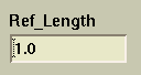
Specifies the reference length in grid units where the Reynolds number is specified. When the value of the reference length is changed, either the value of y+ or Initial Spacing is updated, depending on which is active.
Set the specified value of either the Initial Spacing or the
Boundary-Layer thickness to the selected surface(s). If the
Specify Boundary-Layer Thickness toggle
is set, then the Boundary-Layer Thickness value will be applied to the
surface(s); otherwise the Initial Spacing will be applied. This toggle
must be selected when the surface grid is written in order to use the
Initial Spacing or B-L Thickness values
that have been set. If the toggle is not selected when the surface grid is written, then a uniform
Initial Spacing and Boundary-Layer Thickness
(assuming the Ignore is turned off) will be used
on all surfaces. The initial spacing and
Boundary-Layer Thickness values between adjacent surfaces
are smoothed over several layers to avoid large changes in spacing values which can lead to poor volume
grid quality. Initial spacing and
Boundary-Layer Thickness
may be applied only to Groups
in the geometry or surface grid.
NOTE: If set, variable
initial spacing should be applied to ALL
Groups having the
viscous boundary condition.

Applies the Initial Spacing/Boundary-Layer Thickness to the selected Group if the Set Local Spacing toggle is turned on.
Anisotropic Variables: Boundary-Layer Growth Rates
The maximum boundary-layer growth rate allowed. Both the normal spacing and the maximum growth rate increase geometrically.
Manual Growth Parameters
If the Manual Growth toggle is selected, the growth rate parameters or boundary-layer thicknesses are not automatically calculated. Instead they are specified using the Number of Constant Layers, the Initial Growth multiplier, the Growth Multiplier, and the Maximum Growth rate values. The Initial Normal Spacing value is used to specify the spacing normal to boundary-layer surfaces.
Specifies the number of constant boundary-layer normal spacing layers adjacent to the boundary-layer surface. Boundary-layer normal spacing growth is applied after the specified number of constant spacing layers.
Specifies the initial boundary-layer normal spacing growth multiplier. The multiplier determines the geometrical growth rate at which the boundary layer grid grows.
The growth multiplier adds an additional geometrical growth to the boundary-layer normal spacing growth rate.
Graphical Explanation of Boundary-Layer Growth
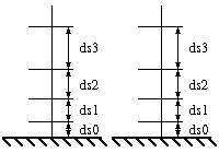
ds0 = Absolute Initial Spacing
ds1 = r1*ds0
ds2 = r2*ds1
ds3 = r3*ds2
r1 = r0 = Initial Growth
r2 = Growth Mult * r1
r3 = Growth Mult * r2
Volume Grid:

The host field allows you to specify which machine you want to run the volume grid generator. If "Local" is specified, the machine that SolidMesh is currently running on will be used. If a valid machine name is specified (one that is accessible to you and that has an executable version of AFLR4) a script file will be generated and a "rsh xterm" command will be generated. A window will be started with the output of the AFLR4 program. When AFLR4 has completed generating the grid, an output file will be generated that can then be read into SolidMesh for visualization of grid quality. NOTE: You probably want to quit SolidMesh and use the -grid option to read in the volume grid due to the amount of memory needed to compute volume grid quality.

Use multi-pass partion mode grid generation. In partition mode, the grid generation is performed one stage at a time and intermediate data is stored in temporary files instead of memory (out of core). This option should be used for large cases with BL generation as it will substantially reduce memory requirements.
Specify that AFLR4 use the boundary conditions, initial spacing, and boundary-layer thickness specified in the tags file instead of those specified in the surface grid file.

Writes only the surface grid, tags file, and the AFLR4 run script file. This allows manual modification of the run script and/or launching of the AFLR4 volume grid generator on a specified machine.

Launches the AFLR4 volume grid generator using the specified options described above as well as the options specified in the Volume Options application. Launching the volume grid generator will write out a surface grid, tags file, and a script with all of the specified options and (if specified) "rsh xterm" the script on the specified machine. Once the volume grid generator is launched, you can still work within SolidMesh.
 |
 |
 |
 |