


Basics
Type in sm at the command line to invoke SolidMesh. A list of the command line options is available here. User-specified preferences may be set in the set-up file.
The SolidMesh Window
The window consists of the drawing area, message area, group edit area, global picking area, global graphics edit area, application area, and application selection area. This may be more evident if you inspect the exploded view of the window.
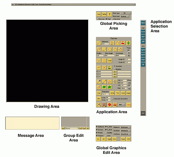
The light blue icons aligned vertically down the extreme right of the screen represent the available applications in SM. These call up their respective applications: File Input/Output, Curves, Surfaces, Utilities, Surface Grid Generation, Volume Grid Generation, Volume Grid Advanced Options, Grid Visualization, Debug, and Color.
View Manipulation of the Drawing Area
The mouse may be used to manipulate the objects which are visible in
the drawing area. The speed of translations, rotations, and zooms are regulated
by the distance the mouse is moved while the respective buttons are held
down. The -mouse command line option can be used
to remap the mouse button functionality.
Translation:
Holding down the left mouse button (default) while moving the mouse in the desired
direction will cause the contents of the drawing area to be moved, or
translated, in the direction of the mouse movement in relation to the screen.
The translation sensitivity can be increased and decreased using the numeric
keypad "*" and "/" keys, respectively.
Rotation:
To rotate the contents of the drawing area, hold down the middle mouse
button (default) and move the cursor in the desired direction of rotation. The rotation
sensitivity can be increased and decreased using the numeric keypad up and down arrow keys,
respectively.
Zoom:
When holding down the right mouse button (default), you can "push away" (zoom
out) the contents of the drawing area by moving the mouse up or to the
left, or "pull to" (zoom in) the contents of the drawing area by moving
the mouse down or to the right. This same operation may be performed using the
mouse scroll wheel. The zoom sensitivity can be increased and decreased using the
numeric keypad "+" and "-" keys, respectively.
A zoom box can be initiated using the "Z"
hotkey.
The center of the zoom box will appear at current mouse location and will expand based on the
mouse position. The zoom box is initiated by the zoom mouse button. The zoom
box can be terminated by the "Esc" key. The amount of zoom is based on the size
of the zoom box. The zoomed image will be re-centered.
Picking:
Use the mouse to pick objects in the drawing area. Instead of holding
down mouse keys, the keys are clicked very quickly while keeping the mouse
in the same location. There are a variety of options available for picking
(see the next section). Each mouse key is mapped to a specific type of object and are
dependent upon the Pick Limit:
- Left Mouse Button: Picks/unpicks a point. Alternatively, the F7 function key may be used to pick/unpick a point.
- Middle Mouse Button: Picks/unpicks a curve. Alternatively, the F8 function key may be used to pick/unpick a curve.
- Right Mouse Button: Picks/unpicks a surface (or use F9) if the pick limit is set to surface, or picks/unpicks a vector (or use F10) if the pick limit is set to vector.
- The F12 function key can be used to pick/unpick the entire contents of a Group.
Global Action Areas
Global Action Areas consist of commands that can be executed at any time by simply clicking on the appropriate button or pulldown. Global action keys are always displayed on the screen regardless of the application that has been activated. The global action keys and their associated functions are as follows:
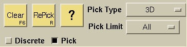

You can clear all objects from the pick list by selecting the Clear button. You can also do this by hitting "Esc" or "F6" on the keyboard.

Repicks the last group of objects picked.

The type of picking to be used can be controlled by the Pick Type
selector.
-
3D: The 3D type indicates that the only pickable objects
are the visible object that the cursor is on. If you try to pick a surface
and your cursor is over a curve, all of the surfaces that share that curve
are picked. The same is true for curves when your cursor is over a point.
You can also choose this type by pressing "3" on the keyboard.
The following information is provided when a single entity is selected:- Vertex/Point: Id and type
- Curve: Id and type
- Surface: Id, type, and group association
- Group: Boundary condition(s) and grid size information
- Everything: If you wish to pick all visible objects of the type specified, you can set the type of picking to Everything. You can easily switch to this type of picking by setting the selector on the screen or just hitting the "e" button on the keyboard.
- Partial banded: If you desire to select one type of object within a certain area of the model without having to select each object of that type separately, you would probably want to use either Partial or Whole banding. Partial banding allows one to pick the objects which are partially within the box created. This is very useful if you have some surfaces or other objects of different sizes. You may wish to pick all of the surfaces in a given area, but by trying to include all of one specific surface you include others which you did not want. Partial banding allows you to include only part of the surface in your box and have it picked. By pressing the b key on the keyboard, a band is activated on the screen. Extend the band (by moving the mouse) to create a bounding box. Once the box encompasses the desired objects, click the appropriate key on the mouse to select the objects that are partially in the box.
- Whole banded: If you desire to select one type of object in a certain area of the model, you may want to use Whole banding. If all of the objects which you would like to choose are in the same general area and there are no more objects of that specific type which could be fully banded when creating the boundary box, you would probably save a lot of time by using this picking type. By pressing the w key, a band is activated on the screen. Extend the band (by moving the mouse) to create a bounding box. Once the box encompasses the desired objects, click the appropriate key on the mouse to select the objects that are completely within the box.
-
Curve Points: When the pointer is positioned over a curve,
center clicking will select points where the curve is discretized.
Then
 can be used to re-interpolate the curve with the points selected.
The number of points selected depends on the resolution
of the curve.
can be used to re-interpolate the curve with the points selected.
The number of points selected depends on the resolution
of the curve.
-
Label: This type of picking allows the user to
pick objects of the specified type by their id. To pick an object, enter
the id into the Global Argument field
 .
Note that when picking by Label, all three types of curves may be selected
if the Pick Limit is set to either Curve, Physical, or
Parametric. You can also choose this type by pressing "l" on the keyboard.
.
Note that when picking by Label, all three types of curves may be selected
if the Pick Limit is set to either Curve, Physical, or
Parametric. You can also choose this type by pressing "l" on the keyboard.

Pick Limit Selector
The Pick Limit selector limits picking to specific types of objects
and items connected or attached to the object.
- All: Traditional pick limits:
- Left MB: Vertex
- Middle MB: Curve
- Right MB: Surface
- Surface: Surfaces and objects attached to a surface:
- Left MB: Point on the interior of a surface.
- Middle MB: Curves defining the surface. For a trimmed surface, the parametric curves defining the trimming loop are selected. For an untrimmed surface, the derived curves are selected.
- Right MB: Surface
- Curve: Curves and objects attached to the curve:
- Left MB: Point on the interior of the curve
- Middle MB: Curve, all three types are selectable: derived curves, parametric curves, and physical curves.
- Right MB: Surfaces adjacent to the curve the mouse is positioned over.
- Point: Vertices and objects attached to vertices are pickable.
- Left MB: Vertex
- Middle MB: Curves connected to the vertex the mouse is positioned over
- Right MB: Surfaces connected to the vertex the mouse is positioned over.
- Vector: Only vectors are pickable. The right mouse button is used to select the vector.
- Parametric: Parametric curves and objects attached to
the parametric curve:
- Left MB: Point on the interior of the parametric curve
- Middle MB: Parametric curve
- Right MB: Surfaces adjacent to the parametric curve the mouse is positioned over.
- Physical: Physical curves and objects attached
to the physical curve:
- Left MB: Point on the interior of the physical curve
- Middle MB: Physical curve
- Right MB: Surfaces adjacent to the physical curve the mouse is positioned over.
-
Trim: Only trimmed surfaces and objects attached
to a trimmed surface are pickable:
- Left MB: Point on the interior of a trimmed surface.
- Middle MB: The parametric curves defining the trimming loop are selected.
- Right MB: Trimmed surface
-
Mesh: Mesh is used with discrete data, i.e. surface grids and volume grids.
- Left MB: Point on the interior of the discrete surface and the containing triangle or quad id is printed in the Message Area. If the Discrete toggle is turned on, then a grid point on the discrete surface is selected and the grid point id is printed in the Message Area.
- Middle MB: Nothing is selectable.
- Right MB: Discrete surface/Group.
-
Group: Selects objects contained in a group. If the cursor is positioned over a Point/Curve/Surface
that is in a group, then
- Left MB: All points in the group are selected.
- Middle MB: All curves in the group are selected.
- Right MB: All surfaces in the group are selected.
-
Composite: Selects all of the component surfaces defined in the
Composite surface definition when any one
component surface is selected.
- Left MB: Nothing is selectable.
- Middle MB: Nothing is selectable.
- Right MB: All surfaces in the composite surface are selected.

Discrete Toggle
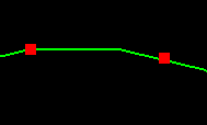
Toggles between discrete and continuous picking. Discrete picking can also be selected by pressing "d" on the keyboard. When picking discretely, an object can only be picked at points that have been explicitly evaluated for display. For example, you can tell where the curve shown below has been evaluated by the break in the line. If the discrete toggle is selected this curve is only pickable at these locations. For example, the point on the left has been picked on the curve at one of these evaluation points. The point on the right has been picked between evaluation points. This is possible when the discrete toggle is off (continuous picking).
Curve Discrete Picking Example
The same is true with surfaces. The surface is only pickable at points where it has been explicitly evaluated (intersections in the wire frame). The point on the right was picked discretely at one of the surface's evaluation points. The point on the left was picked continuously.
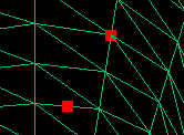
Surface Discrete Picking Example

Pick Toggle
By default the Pick toggle is active in order to pick or select objects. If the Pick toggle is turned off, selected objects can be unpicked. The TAB key can also be used to toggle picking. Alternatively, instead of turning the Pick toggle off, pressing the CONTROL key while picking can be used to unpick a single entity.
Global Argument field

Gives information about the objects picked. Depending on what and how objects were picked, different information is returned.
- Points: If a single point is picked, its coordinates are displayed in the points application. If two points are selected, the distance between is returned in the Message Area. If three points are picked, the angle between them is returned (the second point picked is assumed to be the vertex).
-
Surfaces: If a surface is picked, the display resolution,
number of control points, number of child curves, and any surface grid
boundary conditions are listed in the Message Area. Also, any child
curves of the surface inquired on are automatically selected; and any surface
grid boundary conditions applied to the surface will be reflected in the
toggles in the
 menu (if multiple surfaces are selected when inquired on, only the last
surface's information will be reflected).
menu (if multiple surfaces are selected when inquired on, only the last
surface's information will be reflected). - Curves: If a curve is selected, the curve type, number of control points, display resolution, and arc length are displayed in the Message Area.
-
Vectors: If a vector is selected, the x-y-z components are
displayed in the vector application and the
Message Area. If two vectors are selected, the angle between is displayed
in the Message Area and in the
 angle text field.
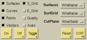
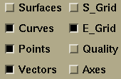
Toggles the visibility of the indicated object type. For example, "surfaces" in the above picture is unselected; so no surfaces will be visible in either the "on" or "off" scene (discussed below), but they can still be selected using the visible objects. For example, when the pick limit (discussed above) is set to curve, a surface could still be selected by right clicking over one of its bounding curves.

There are three types of surface displays available:
- Wireframe: Surfaces appear as wireframes.
- Shaded: Surfaces appear shaded.
- Points: Surfaces appear as points.

There are four types of surface grid displays available:
- Wireframe: Surface grids appear as wireframes.
- Shaded: Surface grids appear shaded.
- Points: Surface grids appear as points.
- Wire/Shad: Surface grids appear shaded with wireframes.

There are five types of cutting plane displays available:
- Wireframe: Cutting planes appear as wireframes.
- Solid: Cutting planes appear shaded as a single color. The default cutting plane color may be changed using the Miscellaneous Entity Color menu.
- ColorMap: Cutting planes appear shaded and are colored by the volume element angles.
- Wire/Solid: Cutting planes appear shaded with overlaid wireframes.
- Wire/Color: Cutting planes appear shaded using the volume element angles with overlaid wireframes.
- Invisible: Cutting planes are not displayed.

Turns all active objects on. Deactivated groups still will not be visible. This command can also be executed using the "o" key on the keyboard. When objects are "on," they are available to the user for manipulation and are visible on the screen.

Turns selected objects off. If nothing is selected, all active objects are turned off. This command can also be executed using the "O" (Shift-o) key. The objects which are turned "off" are placed into a different scene. This is helpful when only certain objects need to be manipulated. All other objects can be removed from the scene so that the view is simplified.

Toggles between the on and off scene. Visible objects become invisible and invisible objects become visible.

You can select the Reset View button to reset the view. This is to eliminate any transformations and to scale the view to only include visible objects. You can also use the numeric keypad button "0" for this command.

If a single point is selected, the center of rotation is set at the picked point. If multiple points are selected, the center of rotation is set at the average location of the selected points. If no points are selected, the previous center of rotation is returned to the center of the view area. Also, pressing F5 with the pointer in the view area changes the center of rotation to whatever the pointer was over.

Delete Button
Removes the selected objects from the model. Objects which are
derived from unpicked objects will not be deleted (for example, a selected
bounding curve of an unselected surface will not be deleted). If
an object is deleted unintentionally, it can be undeleted in the
 menu.
menu.

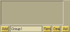
- To create a Group, simply select the desired entities and hit the < Enter > in the
Group Name text field or hit the
 button.
If the Group name already exists, the entities will be added to the existing Group. To
rename a Group, select the desired Group in the Group List editor, type the new name in
the Group Name text field and hit < Enter > .
button.
If the Group name already exists, the entities will be added to the existing Group. To
rename a Group, select the desired Group in the Group List editor, type the new name in
the Group Name text field and hit < Enter > .
- Multiple groups can be selected within the List Window by selecting the Group from the list and using the control and shift keys. All Groups can be selected using the Control-slash (ctrl - /) keystroke.
- A status indicator has been added to the first column of the group name to indicate if the group is On, Off, or Deactive. The o symbol indicates that the group is On, x indicates the group is Off, and - indicates the group is Deactive.
- Objects (points, curves, and surfaces) are placed in groups for a number of reasons. Groups are used to assign boundary conditions to surfaces for volume generation. Groups can also be used during geometry clean up by using activate and deactivate (see the tutorials).

Removes the selected object from its respective group. If a group is selected, the group is removed. The objects are not deleted, only removed from the group. Once all objects have been removed from a particular group, the group name is removed from the list.

Disables the display of the selected group. The objects will no longer appear in either the on or off scene. The group must be reactivated before the grouped objects can be worked with again. NOTE: Although curves and points can be placed in groups, if the parent surface of a point or curve is active the point or curve will also be active.

Activates the display of the selected group. The objects in the
group can now be seen and worked with again.
NOTE: Activate and Deactivate are most useful with large geometries
where the large number of surfaces inhibits picking. All but the
objects being worked with can be deactivated so that the surfaces being
worked with can be turned on, off, and toggled without the other surfaces
getting in the way. See the tutorials
for examples.
 |
 |
 |
 |