


Curves

Curves Applications
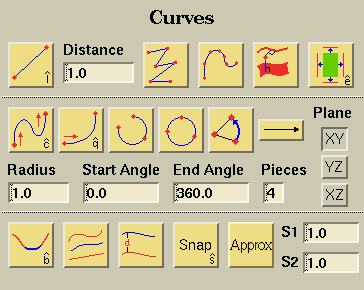
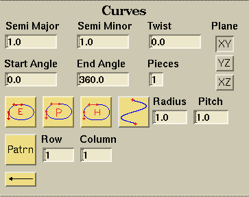
There are two types of curves you can create: physical curves and parametric
curves. Physical curves are curves in space that have no relation to a
surface. Physical curves are used primarily for surface construction in
3D and actual boundary construction in 2D. Parametric curves are specified
within the parametric space of a surface. Within SolidMesh, the parametric
curves are used to trim surfaces in 3D. Parametric curves are not used
in 2D. To create a parametric two-point line, polyline, or interpolated
cubic curve, simply pick the surface before creating the curve. To create
a parametric curve with the other types of curves, create the curve then
project the curve onto the desired surface. Parametric curves are
represented as green curves while physical curves are represented as yellow
curves.
Examples of each button's functionality can be viewed by clicking on
the button.

Creates a line between the selected points. This function can be used several ways with different inputs:
- If only two points are picked, a straight line is created between them.
- If more than two points are picked, a line is created between each pair of points in the order they were picked.
- If points and a surface are selected, the parametric curves in the space of the surface are created.
- If a single point and a vector are picked, a line with the length specified in the distance field is created, starting at the point and extending in the direction indicated by the vector.

The distance field is used to specify the length of lines generated with a point and a vector and the distance to offset curves.

Creates a curve that goes through each point selected in straight line segments (similar to using the create line button with multiple points selected but only one curve is generated). If a surface is selected, a parametric curve attached to the surface selected will be generated.

To create an interpolated cubic curve, pick at least four points and then select the Create interpolated cubic curve button, which will cause an interpolated cubic curve to be generated. The curve is generated based on the order of the points picked. If a surface is selected, a parametric curve attached to the surface selected will be generated.

Creates normal lines from the point selected to the objects (curves and surfaces) selected. The point selected is the starting point for the curves generated. The end points lie at the closest point on the selected objects.

Extracts the bounding curves of the surfaces selected. Also, if a surface and any number of its bounding curves are selected, only those curves will be extracted.

There are 2 ways to create a cubic curve:
-
With 2 points and 2 vectors:
Pick two points and two vectors, then select the Create cubic curve button. The cubic curve is generated between two picked points using two picked vectors (the slope vectors). The first picked vector is applied at the first picked point, and the second picked vector is applied at the second picked point. -
With 2 points and 2 curves:
Pick two points and two curves, then select the Create cubic curve button. The cubic curve is generated between two picked points using two picked curves. The points picked must be vertices of the two curves. The cubic curve will be perpendicular to both picked curves at their endpoints (the picked points).

To generate a quadratic curve, pick two points and a vector, then select the Create quadratic curve button. The slope vector is applied at the first picked point, which is used for the beginning of the quadratic curve.

Scales the weight of the vectors selected when creating a cubic or quadratic curve.

Creates a circular arc based on the inputs provided:
- If 3 points are selected, a circular arc connecting those points is created.
- If 1 point is selected, the values in the start, end, and radius field discussed below are used to create a circular arc in the chosen plane centered at the selected point. NOTE: The plane is chosen from the plane field.
- If no point is selected, a circular arc is created in the same manner as above with the center point given by the values in the X,Y, and Z fields.

To generate a circle, first pick three points which you want to lie on the circle. You must then select the Create circle button. The result will be a circle defined by the three picked points.

To create a circular arc segment, pick three points and then select the Create Arc Segment button. The first point is the center, the second is the start point, and the third is the end point. The arc is generated counter-clockwise from the starting point to the ending point.
The radius field is used to specify the radius of a circular arc which is generated using the various fields, instead of from three points.
The start angle field determines the starting angle in degrees of the circular arc or conic section generated using the fields. This field does not affect circular arcs generated by using three points.
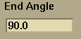
The end angle field determines the ending angle in degrees of the circular arc or conic section generated using the fields. This field does not affect circular arcs generated by using three points.

The pieces field is only used along with the start and end angle fields. This field determines the number of pieces in which the circular arc or conic section is created.
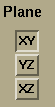
The plane field determines in which plane the circular arc or conic section is to be generated. This field only affects circular arcs generated using the various fields options.

To generate a curve connecting the two closest endpoints of two curves, pick the curves and then select the Blend curves button. By default the blended curve goes between the two closest endpoints, but this can be overridden by picking the desired endpoints. The generated curve starts parallel to the picked curves at the endpoints and then connects the two curves.

To generate a curve that is the average of any number of picked curves, first pick the curves and then select the Average picked curves button. The result will be the creation of the new average curve.

Creates a curve that is offset from the picked curve. To create a curve which is the offset of another, pick the curve to be offset and then select the Create Offset curve button. The new curve is the specified distance from the picked curve in the direction computed by the cross product of the normal to the specified plane and the local tangent vector. The distance is set by the distance field. The plane is chosen from the plane field.

To create a new curve by moving the endpoint of one curve to a new place while still keeping the basic form of the original curve, you should use the Snap button. This can also be done with multiple curves, but only using one point. First pick a single point and one or more curves, then select the Snap button. The new curve(s) will start at the endpoint of the picked curve(s) that is the greatest distance away from the picked point. The new curve(s) will follow the form of the picked curve(s), but the picked point will become the new endpoint(s). It will take the place of the endpoint(s) closest to it. If the two picked curves are parametric curves from the same surface, the resulting curve will also be a parametric curve of that surface.

Creates a new approximated curve from the selected curve by using the display resolution to spline a new curve. Select the curve to be approximated and click Approx. Produces the same result as setting the Pick Type to Curve Pts., middle clicking over a curve, and creating an interpolated cubic curve. Again, the accuracy of the approximation depends on the display resolution.

Go to the Curves palette for creating conic sections.

This field is used to set the length of the semi-major axis.

This field is used to set the length of the semi-minor axis.

This field is used to specify the twist or rotation (in degrees) of the conic being created. The rotation is about the axis normal to the specified plane.

Creates an elliptic arc based on the inputs provided:
- If 1 point is selected, the values in the start angle, end angle, semi-major, semi-minor, and twist fields are used to create an elliptic arc in the chosen plane centered at the selected point. NOTE: The plane is chosen from the plane field.
- If no point is selected, an elliptic arc is created in the same manner as above with the center point given by the values in the X,Y,Z fields.
- Two points and two vectors
- Three points

Creates a parabolic arc based on the inputs provided:
- If 1 point is selected, the values in the start angle, end angle, semi-major, semi-minor, and twist fields are used to create a parabolic arc in the chosen plane centered at the selected point. NOTE: The plane is chosen from the plane field.
- If no point is selected, a parabolic arc is created in the same manner as above with the center point given by the values in the X,Y,Z fields.
- Two points and two vectors
- Three points

Creates a hyperbolic arc based on the inputs provided:
- If 1 point is selected, the values in the start angle, end angle, semi-major, semi-minor, and twist fields are used to create a hyperbolic arc in the chosen plane centered at the selected point. NOTE: The plane is chosen from the plane field.
- If no point is selected, a hyperbolic arc is created in the same manner as above with the center point given by the values in the X,Y,Z fields.
- Two points and two vectors
- Three points

Creates a helix based on the pitch, radius, and plane field. The helix will be centered about either the selected point or by a point specified in the X,Y, and Z fields. The direction of travel for the helix is normal to the specified plane. The plane can be specified using either the plane field or using two normal vectors.

This field is used to specify the radius of the helix.

This field is used to specify the pitch of the helix. The pitch is the distance the helix travels in one revolution, measured along the helix axis.

Return to Curves main palette
Return to the main Curves palette.
 |
 |
 |
 |