


Tutorials: Assigning Point Spacing
Point spacings are a function of the geometry. Areas with high curvature or a lot of detail require small point spacings and lots of points. Also, places where high activity in the solution is expected require tight spacings. Areas which are mostly planar or little activity is expected in the solution don't require lots of points and will have larger point spacings. The previous tutorial was intended to illustrate how to control point spacings and density. This tutorial is to illustrate methods in actually applying individual point spacings and point grouping. You can continue from the last step of the Surface Splitting for Point Efficiency Tutorial or download the file flying_minnow_clean_split.igs.gz.
1. Read the file flying_minnow_clean_split.igs.gz in with gluing and trimming enabled.
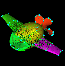
2. Points can be added to groups like surfaces, so groups of
points that will have the same spacings can be added to a group for easier
spacing. Click all the groups except Prop and  .
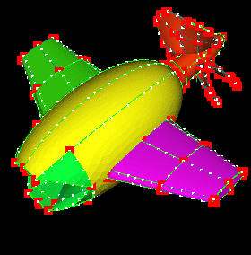
Select the points around the outer edge of all five prop blades including the ones
at the base as shown. Enter "BladeOuterPoints" in the name field
of the group editor and click
.
Select the points around the outer edge of all five prop blades including the ones
at the base as shown. Enter "BladeOuterPoints" in the name field
of the group editor and click  .
FYI: Another easy way of setting the point spacing on the prop
would be to do it before rotating and creating the other 4 blades (see
the end of the last tutorial). The point spacings are retained when
rotating, translating, ... This method is perhaps easier/cleaner
than grouping points. For large geometries with many groups, these
extraneous groups may get in the way.
.
FYI: Another easy way of setting the point spacing on the prop
would be to do it before rotating and creating the other 4 blades (see
the end of the last tutorial). The point spacings are retained when
rotating, translating, ... This method is perhaps easier/cleaner
than grouping points. For large geometries with many groups, these
extraneous groups may get in the way.
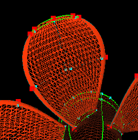
3. Select the next ring of points just inside the ones selected
in the previous step including the two in the middle of the blade at the
base. Be sure to get the points on both sides of the blade on all
five blades. Enter "BladeMidPoints" in the name field of the group
editor and click .
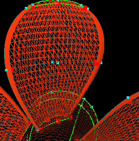
4. Select the innermost point on both sides of the blade on
each of the five blades. Enter "BladeInnerPoints" in the name field
of the group editor and click .
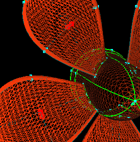
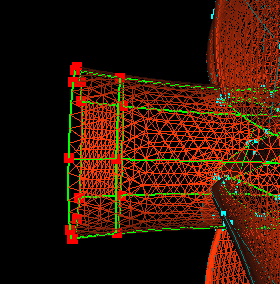
5. Select all the points at the front of the hub (where it meets
the base) as shown. Enter "HubCollarPoints" in the name field of
the group editor and click .
6. Click the Prop group and .
Click the LeftWing and RightWing groups and  .
Select the points on the leading and trailing edges of both wings.
Enter "LeadTrailPoints" in the name field of the group
editor and click .
.
Select the points on the leading and trailing edges of both wings.
Enter "LeadTrailPoints" in the name field of the group
editor and click .
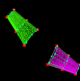
7. Select the next inner course of points. Be sure to get
the points on both sides, top and bottom, of the airfoil. Enter "WingMidPoints"
in the name field of the group editor
and click .
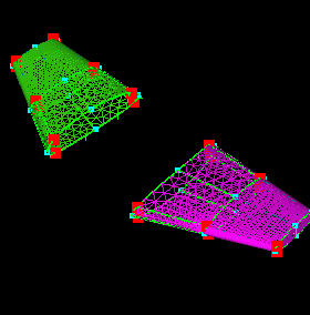
8. Select the innermost course of points. Again, be sure
to get the points on both sides of the airfoil. Enter "WingInnerPoints"
in the name field of the group editor
and click .
This finishes the grouping of the most important points for this geometry.
The next step is to start assigning point spacings to the groups and individual
points not in groups.
all groups. (there is no need to
groups with only points. they will activate when the parent objects,
surfaces, are activated).
9. One way to start is to hit "e" to set the pick type to "Everything"
and pick all points. Enter a reasonable value, about 0.75, for the
point spacing of most points in  and
and  .
This value will be the "default" and then you can go back and enrich the
grid in areas that need tighter spacings.
.
This value will be the "default" and then you can go back and enrich the
grid in areas that need tighter spacings.
10. Hit "Esc" to clear the pick list and  .
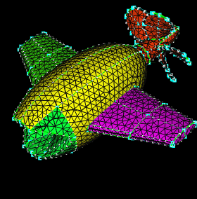
Use the Global Graphics Edit Area to
turn the surfaces off and display the Surf Grid as Wire/Shad. You
can see the spacing of 0.75 is too coarse for some parts of the grid (leading
and trailing edges of the wings, the prop, ...), but in areas of little
activity (top of the body, mouth area), this spacing is OK. For a
real geometry shaped like the Mouth, enrichment would probably be necessary,
but for illustration and to keep the grid small, these areas will be left
coarse.
.
Use the Global Graphics Edit Area to
turn the surfaces off and display the Surf Grid as Wire/Shad. You
can see the spacing of 0.75 is too coarse for some parts of the grid (leading
and trailing edges of the wings, the prop, ...), but in areas of little
activity (top of the body, mouth area), this spacing is OK. For a
real geometry shaped like the Mouth, enrichment would probably be necessary,
but for illustration and to keep the grid small, these areas will be left
coarse.
11. Now we will enrich critical areas.
Click the LeadTrailPoints
and WingMidPoints groups. Change the value in the
field to 0.1 and .
Hit "Esc" to clear the pick list. Click the WingInnerPoints group and
change the spacing to 0.3,
and .
Hit "Esc" to clear the pick list. You can see having the surface
split enables you to pack the points towards the leading and trailing edges
where they are needed and leave them out in the middle where they may not
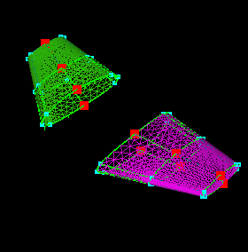
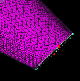
be needed. The wingtip is still a little coarse, so select the two
points shown, enter 0.5 in the ratio field and click  .
This takes the spacing at the points selected and multiplies them by 0.5.
Repeat this for the other two points on the opposite wingtip. Click
.
.
This takes the spacing at the points selected and multiplies them by 0.5.
Repeat this for the other two points on the opposite wingtip. Click
.
12. Click the Mouth, Body, and both Wing groups and
.
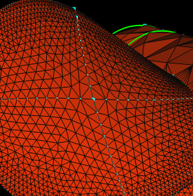
As you can see, with the current spacings, the prop is far too coarse.
Click the BladeOuterPoints group, enter 0.025 in the spacing field and .
Hit "Esc". Click the BladeMidPoints group, enter 0.045 for the spacing
and .
Hit "Esc". Click the BladeInnerPoints group, enter 0.25 for the spacing,
and .
Click .
You can see this greatly increases the point density around the perimeter
of the blade.
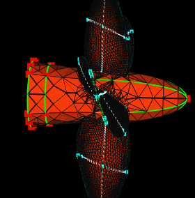
13. Hit "esc". Click the HubCollarPoints group and select the
point on the tip of the hub as shown. Set the spacing at 0.3 and
and .
14. The grid is still too coarse between the blades. Select
the point on the blade closest to the selected curve. Click the  to get the point's spacing and .
This creates a point on the selected curve at the closest point to the
selected point and gives it the spacing in the spacing field. Hit
"esc".
to get the point's spacing and .
This creates a point on the selected curve at the closest point to the
selected point and gives it the spacing in the spacing field. Hit
"esc".
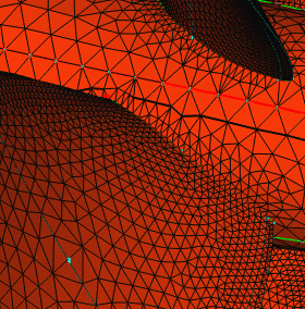
15. Select the point shown on the opposite blade and the
same curve. Click the
to get the point's spacing and .
Hit "esc". You can see this increases the number of points between
the blades. Repeat steps 14 and 15 for the other four curves between
the blades.
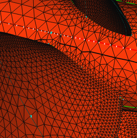
16. The hub is still too coarse, so select the HubCollarPoints
group and the point at the nose of the hub (like in step 13). Click
to see what the current spacing is. Change the spacing to 0.2, ,
and .
Hit "esc".
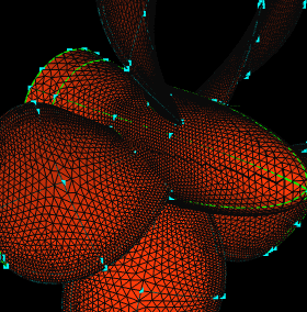
17. Click the Mouth, Body, and both Wing groups and .
and click Quality in the Graphics Edit Area
. The message window reports the surface angle max and min values.
The max angle should be less than 120o, but it's not.
In the Graphics Edit Area disable everything
but Quality. Click  . Rotating in the view screen reveals several yellow "flakes."
These are the surfaces elements with angles greater than 120o.
Turn the curves and points back on. Several of these "flakes" are
under the LeftWing. Select the point shown and
. Rotating in the view screen reveals several yellow "flakes."
These are the surfaces elements with angles greater than 120o.
Turn the curves and points back on. Several of these "flakes" are
under the LeftWing. Select the point shown and  .
.
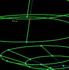
18. Turn the surfaces and S_grid back on. You can easily see the problem. This is probably due to a bad surface parameterization. Select the surfaces shown.
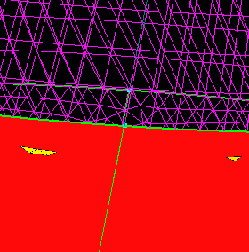
19. In the  menu, change the point insertion from Physical to Approximate and
  .
Click .
Approximate is not quite as accurate as Physical (see
for more information), but the only other way to fix the problem would
be to replace the surfaces with a carpet or just rebuild them (if possible).
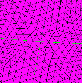
If you, again, turn the quality on, you can see the problem has been corrected,
and the max angle is below 120.
.
Click .
Approximate is not quite as accurate as Physical (see
for more information), but the only other way to fix the problem would
be to replace the surfaces with a carpet or just rebuild them (if possible).
If you, again, turn the quality on, you can see the problem has been corrected,
and the max angle is below 120.
20. Save your work for use in the next tutorial.
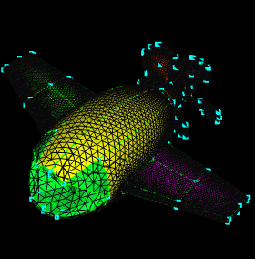
The final step in the grid generation process is to build the outer boundary, apply boundary conditions, and generate the volume grid. This will be covered in the next tutorial: Volume Generation Tutorial.
 |
 |
 |
 |