


Tutorials: Surface Splitting for Point Efficiency
Large complex geometries require tight spacings and lots of points to resolve them. In SolidMesh, point spacings are applied to the end points of a curve and the number of points required is calculated automatically. If tight spacings are applied to both ends of a curve (at the leading and trailing edge of an airfoil, for example), the spacing will be tight at every point along the curve, even where tight spacing might not be required. To help conserve points, the curve could be split in two pieces, so a larger point spacing can be applied in the middle, packing the points to either end where they are needed and removing them from the middle where they may not be required. This tutorial covers point saving techniques: how to split an airfoil shaped object and a propeller blade to localize packing and minimize the point requirement. To start, download flying_minnow_clean.igs.gz or continue with the final product of the CAD clean-up tutorial. REMEMBER: If you save in the middle of this tutorial and exit, read the file back in with gluing disabled when you start over.
1. Continue from the last step of the CAD Clean-up tutorial or
download and read in flying_minnow_clean.igs.gz
with gluing disabled (-ng) and trimming enabled (see  for help).
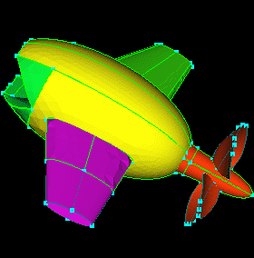
2. Starting with the wings, click the Mouth, Prop, and Body groups
and  .
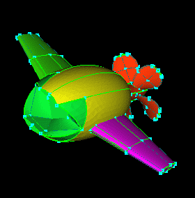
Looking at the wings, the green wing is split around the wing to pack points
towards the leading and trailing edges of the airfoil, reducing the number
of points in the middle. The purple wing is split along the surface
to pack points at the body and wing tip. If wings were split in both
directions, around the airfoil (like the green surfaces) and along the
airfoil (like the purple surfaces), points would be localized to the areas
that were most critical.
.
Looking at the wings, the green wing is split around the wing to pack points
towards the leading and trailing edges of the airfoil, reducing the number
of points in the middle. The purple wing is split along the surface
to pack points at the body and wing tip. If wings were split in both
directions, around the airfoil (like the green surfaces) and along the
airfoil (like the purple surfaces), points would be localized to the areas
that were most critical.
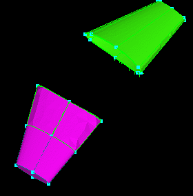
3. Click the RightWing group and .
Select an appropriate point close to the leading edge of the airfoil.
Select the surface shown (leading edge, upper surface) and  .
.
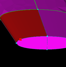
4. Repeat for the other surfaces front and back, top, and bottom. Exactly where the surface is split is really dependent on the geometry. Basically, you want to split (add control curves) in areas of high curvature or activity (in the solution). This will allow you to pack points where they are needed. The surfaces on the end will then need to be trimmed to complete the connectivity.
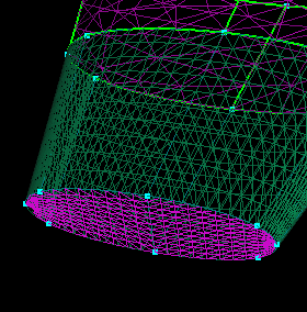
5. Select the surfaces on the end and  .
Then, select the point and parametric shown and .
REMEMBER: When picking parametrics, set the pick limit to "Parametric,"
and when picking points set the pick limit to "Point" otherwise you may
pick points on the interior of a curve or surface.
.
Then, select the point and parametric shown and .
REMEMBER: When picking parametrics, set the pick limit to "Parametric,"
and when picking points set the pick limit to "Point" otherwise you may
pick points on the interior of a curve or surface.
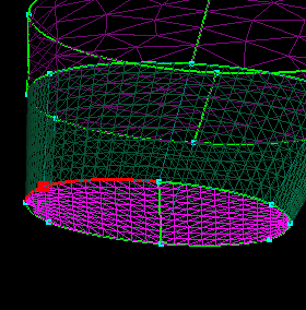
6. Select the point and parametric shown and .
NOTE: You can be sure the parametrics you are picking are associated
with the end surfaces because before step 5 there were no other parametric
curves around those surfaces. Had there been other parametrics, associated
with a neighboring surface possibly, you wouldn't be able to pick the proper
curve with any certainty. In that case it's best to turn the surface
you're trying to trim off (by itself) and toggle. That way you can know
you are splitting the correct curves (those associated with the surface
you want to trim).
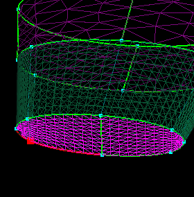
7. Select the surface and  .
Repeat steps 5 and 6 for the other tip surface.
.
Repeat steps 5 and 6 for the other tip surface.
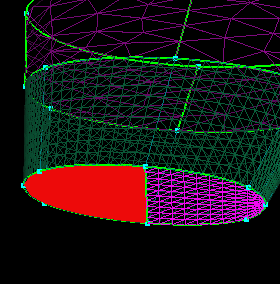
8. To continue the splits from step 3 and 4 up to the body, the
trimmed surfaces (that meet the body, trimmed in the last tutorial) will
have to be deleted. Select the 4 surfaces shown and
 .
.
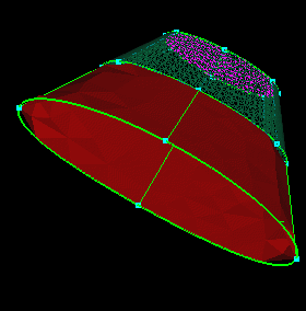
9. You should also select the parametrics used to create the
trimmed surfaces just deleted and
.
This is necessary to keep your geometry clean. Splitting a surface
has the effect of creating 2 new surfaces from the original and deleting
it. If you didn't remove the original surface's parametrics you would
effectively have lingering parametrics not associated with any surface
(at least any working surface). Also, if you didn't read the file
in with no gluing, some of the curves might not disappear. Curves
must be unglued before deleting. Also, when deleting curves, don't
worry if you accidentally select the bounding curve of a surface.
They can not be deleted until the surface is deleted.
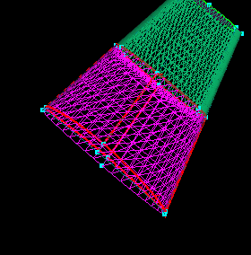
10. Select the point and surface shown (leading edge, upper surface)
and .
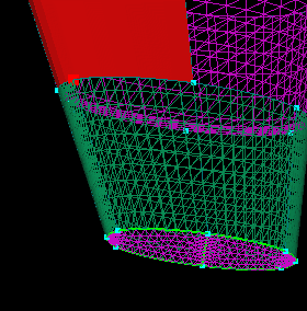
11. Repeat for the other 3 surfaces around the airfoil.
Select all of the new surfaces, click the LeftWing group and  .
Also, click the Body group and
.
Also, click the Body group and  .
.
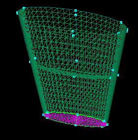
12. The new LeftWing surfaces and the selected Body surface need
to be re-trimmed to establish the new connectivity between the surfaces.
Select the surface shown and
.
Select the curves that created the airfoil shaped cut-out in the Body surface
and
.
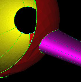
13. Select the surfaces shown (1 body surface and 8 wing surfaces,
the surfaces shown in the next step are those picked in this step),  ,
and
,
and  .
.  and increase the display resolution to
51x51. Also select the yellow body surface then the intersecting
purple surfaces (in that order) and
and increase the display resolution to
51x51. Also select the yellow body surface then the intersecting
purple surfaces (in that order) and  .
.
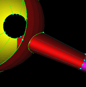
14. Select the body surface and .
and click .
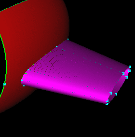
15. Select the LeftWing surfaces shown and .
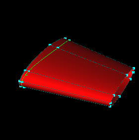
16. Select the two parametrics shown (you will have to pick twice
over the curve shown to get both curves, one from each surface).
Select the point shown and .
Repeat for the other groups of curves around the wing.
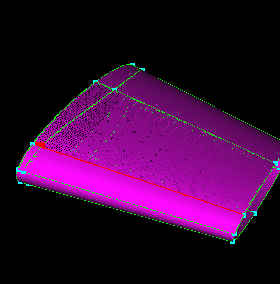
17. Select the unwanted curves (the parametrics to the left of
the intersection line) shown and
.
Select the surfaces and .
Click the LeftWing group and .
Click the RightWing group and .
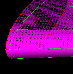
18. Select the surfaces shown and
.
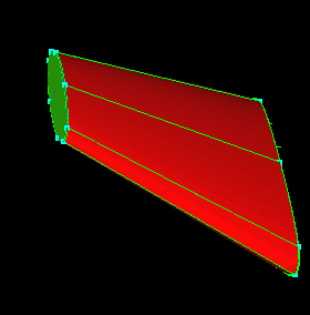
19. Hit "r", "e", and click the middle mouse button to select
all the parametrics that were used to create the trimmed surfaces just
deleted. This is done for the reason stated in step 9, to keep
the geometry clean. Click  to get rid of the points left at the intersection. These are still
visible because they were glued to the end points of some of the curves
just deleted. They actually belong to the curves of the Body surfaces
that isn't visible. The Child button sorts this out and turns them
off. Hit "3", "c" and select an appropriate point (somewhere in the
middle between body and wing tip) on the bounding curve of one of the surfaces.
Select the surface shown and .
to get rid of the points left at the intersection. These are still
visible because they were glued to the end points of some of the curves
just deleted. They actually belong to the curves of the Body surfaces
that isn't visible. The Child button sorts this out and turns them
off. Hit "3", "c" and select an appropriate point (somewhere in the
middle between body and wing tip) on the bounding curve of one of the surfaces.
Select the surface shown and .
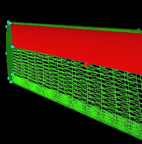
20. Select the point and surface shown and .
Repeat until all of the surfaces extending from the body have been split
creating a curve running around the circumference of the wing. Select the
new surfaces, click the RightWing group, and .
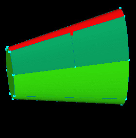
21. ,
select the Body surface shown (the surfaces that intersect the RightWing
in the other scene) selected and
.
Select the airfoil shaped group of parametrics in the middle of the surface
(the curves that cut the airfoil shaped hole in the trimmed surface just
deleted) and
.
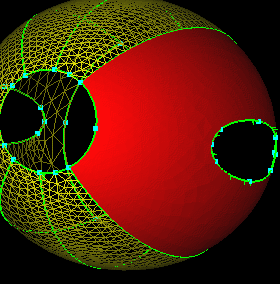
22. Re-select the now untrimmed surface, ,
and select the 8 RightWing surfaces (the ones that intersect the body)
shown. Increase the display resolution to 51x51.
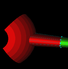
23.
and . ,
select the surface shown, and .
FYI: The reason RePick worked to produce the proper intersection is
because it retains picking order (body surface first, then the intersecting
wing surfaces)
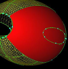
24. ,
select the surfaces shown (the 8 just intersected with the body) and .
Also, trim the surfaces like in steps 16 and 17. This finishes
the splitting of the wings. The wings are now split so that a tight
spacing can now be applied to the leading and trailing edges while using
the control curve in the middle to coarsen the middle of the airfoil.
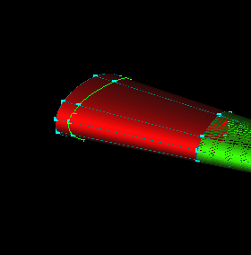
25. Click the Body and RightWing groups and .
Click the Prop group and .
Prop blades are similar to airfoils in that they need more points around
the perimeter of the blade and fewer in the middle. The prop can
also be split to achieve a more efficient use of points.
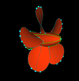
26. Select all the surfaces of one of the blades, ,
and .
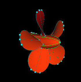
27. Select an appropriate point (indicated by the arrow) along
the surface, select the surface, and .
Continue the split around the blade tip. Select the new surfaces, click
the Prop group and .
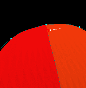
28. Select an appropriate point (not too close to the leading
edge, but then again not too far, see the next picture for a better idea)
along the bounding curve at the base of the blade. Select the blade
surface and .
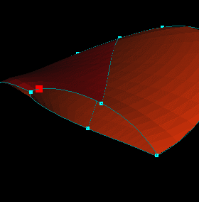
29. Select a similar point on the lower bounding curve.
Select the surface and .
Repeat steps 28 and 29 for the two surfaces opposite the curve in the middle
of the blade.
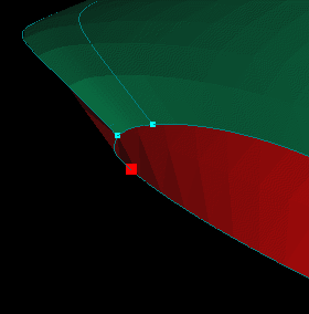
30. Select a point close to the middle of the blade, select the
surface shown, and .
Continue the split around the blade. Select the new surfaces, click
the Prop group, and .
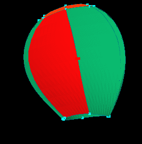
31. Select the 4 surfaces shown (the ones on the back side of
the blade are selected also even though its hard to see in the picture)
and .
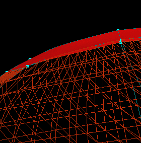
32. Select the parametric curve and point shown and .
Again, use "Param" and "Point" pick limits when picking the parametric
and point, respectively, so you get the right curve and split it at the
correct point.
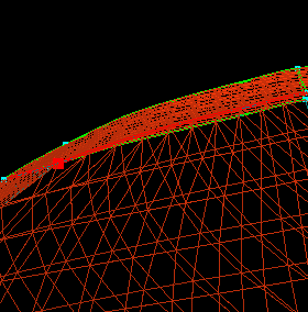
33. Select the surface and .
Repeat for the other three surfaces.
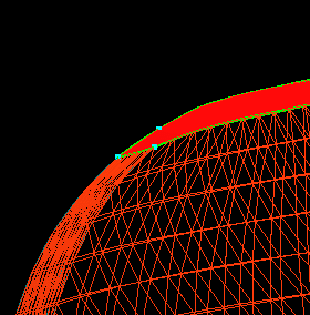
34. ,
select the surface shown (the hub surfaces below the blade you're working
on), and
.
Also, select the parametrics that made up the airfoil shaped hole and
.
Select the now untrimmed surface and increase the display
resolution to 41x41.
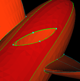
35. ,
select the 8 curves at the base of the blade (as shown).
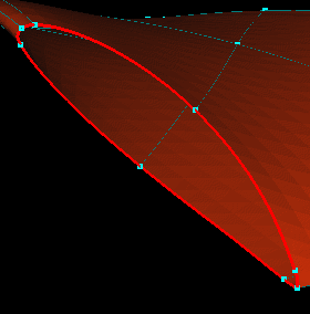
36. ,
select the surface shown and  .
Re-select the surface and .
This blade happens to lie exactly on the hub at all points, so only a projection
of its curves is necessary. Had the blade intersected the hub, an
intersection followed by trimming the blade and hub, like what was done with the wings previously,
would be necessary.
.
Re-select the surface and .
This blade happens to lie exactly on the hub at all points, so only a projection
of its curves is necessary. Had the blade intersected the hub, an
intersection followed by trimming the blade and hub, like what was done with the wings previously,
would be necessary.
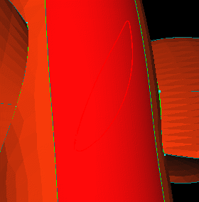
37. Since the other four blades are simply rotations of the split
blade, there is no need to repeat the work for the other blades.
They can be recreated by rotating the split blade. Select the surface
trimmed in the previous step, ,
and click .
Select the blades and hub surfaces shown (all surfaces of the other four
blades and corresponding hub surfaces) and
.
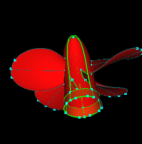
38. Select the hub surfaces again (since the hub surfaces were
trimmed, the deleting in the previous step just removed the trimmed surfaces.
The underlying surfaces and parametrics remain), click  (this selects the surfaces' parametric children), and
.
(this selects the surfaces' parametric children), and
.
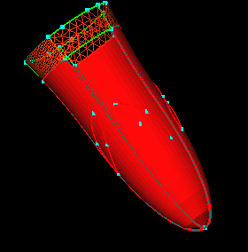
39. ,
select the blade surfaces and the hub, and select the point shown (the
point selected is the one at the nose of the hub and can be seen in the
lower right corner of the picture). Since the rotation will be about
the x axis, no vector needs to be selected. Click the VX in the 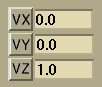 ,
change the value in the
,
change the value in the  field
to 4, and change the value in the
field
to 4, and change the value in the  to 72.
  .
This completes splitting the blades for efficient point use.
.
This completes splitting the blades for efficient point use.
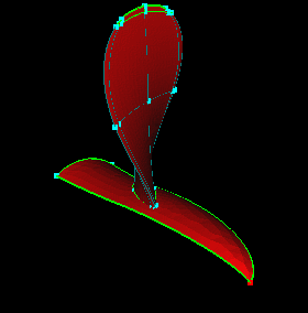
40. Click  ,
click all the group names, and .
,
click all the group names, and .  and
and .
The message should report:
Integrity check passed!
.
The message should report:
Integrity check passed!
0 Edges Picked
Save your model for use in the next tutorial.
This completes the splitting of the surfaces for point efficiency. The next task towards generating a volume grid is to specify appropriate point spacings on all points. This is covered in the next tutorial: Assigning Point Spacings.
 |
 |
 |
 |