


File Input/Output

File I/O Applications
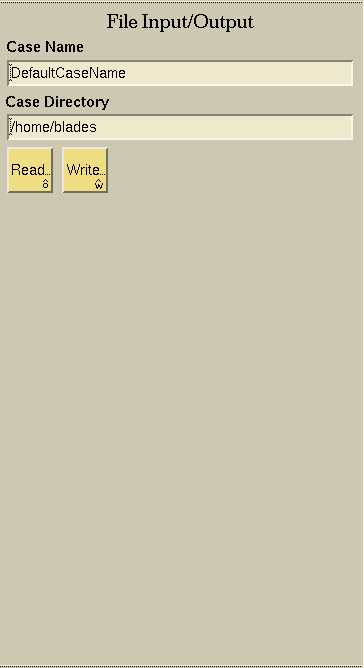
The FileI/O application is used to access geometries or grids from existing cases or to create output files for geometries or grids created or modified in SolidMesh. Related files are organized under a common Case Name: The Case Name has no file extension. File extensions are included in names of the constituent files (grids, geometries, etc.) of a case and are uniquely determined by the file type. SolidMesh automatically appends the proper file extension to the Case Name during the writing of an output file (as in "CaseName.Ext").

The Case Name is the general name of all files common to the given "case," without any file extensions. When changed during a SolidMesh session, all subsequent output from SolidMesh will use the new Case Name.

The Case Directory is the complete path name of the directory where the case files are stored. When changed, all subsequent input and output operations will reference the new Case Directory.

Read or open a new file. The Read button invokes a file selection window to select the desired file.

Write or save a file. The Write button invokes
a file selection window to allow the user
to write to the specified file.
Read File options
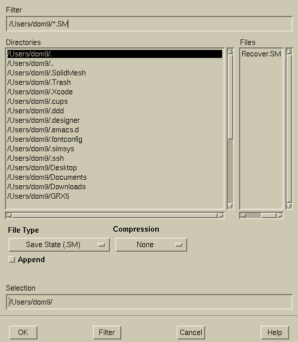
In the SM Browse and Read File Window, there are four fields. The
Directories field allows the user to browse through directories and select the
desired directory. The Filter field displays the choice and
the file extensions currently being used in the search. The Files
field will display the files in that directory that match the current
filter selection. The file filter selection can be updated by either changing the
file type selector or typing in the Filter field
and clicking the Filter button.
To select a file to read, either click the file name listed in
the Files field and the file name will be displayed in the Selection
field or simply type the filename in the Selection field.
The OK button reads the file listed in the Selection field.
The Cancel button does not read any files and returns back to the main SolidMesh application.
Additional options are available for Plot3D and XYZ files,
grid files, discrete geometry,
and CAPRI imported geometry.
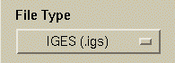
The File Type menu is used to determine the type of information read into SolidMesh. Valid standard input types are Save State, IGES and a variety of grid file types. There are 10 grid file types that can be read by SolidMesh. With a license of CAPRI, various native CAD file types can be imported. Standard file formats for the various file types can be found below:
- Save State: .SM
- IGES: .igs
- STEP: .stp (available through CAPRI)
- OpenCASCADE: .BRep (available through CAPRI)
- UniGraphics (NX): .prt (available through CAPRI)
- Pro/Engineer: .prt (available through CAPRI)
- Pro/Engineer: .asm (available through CAPRI)
- Catia V5: .CATPART (available through CAPRI)
- Catia V5: .CATPRODUCT (available through CAPRI)
- SolidWorks: .sldprt (available through CAPRI)
- SolidWorks: .sldasm (available through CAPRI)
- Parasolid: .xmt_txt (available through CAPRI)
- Plot3D: .p3d
- XYZ: .xyz
- Surface grid: .surf
- UGRID volume grid: .ugrid
- FGRID/UFAST volume grid: .fgrid
- VGRID volume grid: .cogsg
- NASTRAN volume grid: .nas
- CGNS volume grid: .cgns
- Cart3D surface triangulation (Tri file): .tri
- Stereolithography: .stl
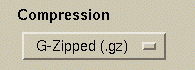
Compression types:
- Compressed: .Z
- G-zipped: .gz
- bzipped: .bz or .bz2
- No compression: No file extension
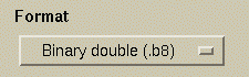
Format Specifications:
UGRID,
Plot3D, and
FGRID/UFAST grid files may include the
following format specifications:
- unformatted single precision: .r4
- unformatted double precision: .r8
- binary single precision: .b4
- binary double precision: .b8
- ascii (formatted): No file extension
Examples:
- IGES file: filename.igs
- IGES compressed: filename.igs.Z
- IGES gzipped: filename.igs.gz
- Formatted Plot3D: filename.p3d
- Formatted Plot3D compressed: filename.p3d.Z
- Formatted Plot3D g-zipped: filename.p3d.gz
- Unformatted Plot3D single precision linear interpolation: filename.r4.p3D
- Binary Plot3D double precision gzipped: filename.b8.p3d.gz

Before reading in a new file, it must be determined what to do with the data for the current file: either keep the existing data while importing the additional data from the new file, or remove the current data and start afresh with the new file. The Append toggle allows you to dictate if the next file read in is appended to the current model (blacken the radio button) or if the current model is removed prior to reading in the new case. The default is to remove the current model prior to reading in the new case.

You can determine if the geometries in the next file that is read are glued (blacken the radio button) or not by setting your preference with the Glue toggle. The default is to glue the model, but the "no glue" command may prove to be very useful when there are changes to be made to the model. This toggle only appears when the IGES, Plot3D, or XYZ file types are selected. The command line options for these actions are "-glue" to glue (which is the default), and "-noglue" or "-ng" to not glue.

You can determine if the geometry in the next file that is read is trimmed (blacken the radio button) or not by setting your preference with the Trim toggle. The default is to trim the model, but the "no trim" command may prove to be very useful when there are changes to be made to the model. This toggle only appears when the IGES file types are selected. The command line options for these actions are "-trim" to trim (which is the default), and "-notrim" or "-nt" to not trim.

You can override the tolerance that is saved with the file
you are about to read in by selecting the Use current tolerance
toggle (blacken the radio button). The tolerance is set in the
Tolerance text field on the
Global Topology Palette.
You can use the tolerance that you
are currently using within the SolidMesh program. This is very helpful
if you are appending a file and want everything to use the same tolerance.
The default for this is to not use the current tolerance (the radio button
is not darkened). This toggle only appears when the
IGES,
Plot3D,
or XYZ file types are selected. The
command line option
for this action is "-tol Tolerance" (where the tolerance desired should
be filled in for "Tolerance").
NOTE: You can find more information on gluing, trimming, save
state, and tolerance, by viewing the Basics page under Starting
SolidMesh

You can choose if you want the save state information read
in along with the geometry by selecting your preference with the Save state
toggle. The save state information is grid information that is
in every
IGES
file written out by
SolidMesh. If the radio button is darkened,
the information will be read in. This is the default. This toggle only
appears when the
IGES
file type
is selected. You may also use "-savestate"
["-ss"] and "-nosavestate" ["-nss"] at the
command line to invoke these actions.
Plot3D and XYZ file format options
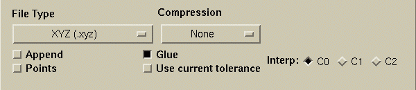

There are three types of interpolations that can be used for
Plot3D
and XYZ files:
- C0: Linear interpolation
- C1: First order cubic interpolation
- C2: Second order cubic interpolation

If this option is selected when reading XYZ files, then
the points are simply read in and no curve is interpolated through them.
The command line option for this action is
"-xyzp".
Grid file format options
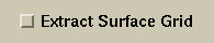
For the volume grid formats, UGRID, FGRID/UFAST, NASTRAN, and CGNS, the surface grid may be extracted from the volume grid and read in. The command line option for this action is -extractsurf.
Toggle used to specify whether to retain the volume id flags used with the following
volume grid formats:

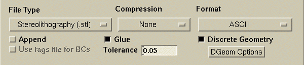
Use this option to enforce the volume grid generation boundary conditions specified in the tags file. The command line option for this action is -tags.

This field is used to specify the tolerance to determine if nodes are coincident when processing
STL files.
This is a relative tolerance based on the local edge length. For example, a value of
0.05 means that two nodes will be considered coincident if the distance between them is less than
5% of the of the minimum edge length attached to the nodes. The tolerance can be specified via the
command line using the -stltol option.
Discrete Geometry options
Use this option to treat the discrete surface triangulation as the underlying geometry. This functionality will allow the generation of a new surface grid using the original triangulation as the underlying geometry. A features identification algorithm identifies the topology based on features in the discrete triangulation and on existing topological boundaries specified in the triangulation. The user will then be prompted to manually add or remove edges to complete the topology definition. Once the topology is extracted, geometric surfaces are constructed and can be used like traditional NURBS-based geometric surfaces. The command line option for this action is -discretegeometry or -dg.
The discrete surface triangulation may be specified in any of the input grid formats:
surface grid,
UGRID volume grid,
FGRID/UFAST volume grid,
VGRID volume grid,
NASTRAN volume grid,
CGNS volume grid,
Cart3D surface triangulation, and
stereolithography.
If the input surface mesh contains quadrilateral faces, they are split into triangles. For the
volume grid formats, the boundary surfaces are extracted and used as the discrete geometry.
NOTE: Curves extracted from discrete geometry may be used as
input to most CAD surface and topology
operations. Note that they may not currently be
split. Development is ongoing.
This button invokes the Discrete Geometry Feature Identification Options dialog.
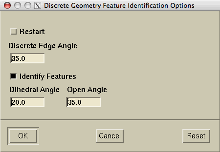
Used to restart from a previous topology definition. The topology definition should reside in a file called casename.dgt. If this option is invoked, the feature detection algorithm will be bypassed. The discrete geometry restart can be specified via the command line option using the -dgrestart option.
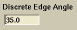
Used to specify the discrete edge angle threshold (in degrees) used for feature identification. The discrete edge angle is the angle between adjacent boundary edges. Edges with angles greater than the specified threshold will be considered candidate features. The discrete angle threshold can be specified via the command line using the -dgedgeangle option.
Used to specify whether or not to use the feature identification capability to extract topological boundaries based on geometric features. If this toggle is not selected, the feature identification algorithm is not used and only the existing or specified topology boundaries are used. The command line option to not use the feature identification algorithm is -nofeatureid.
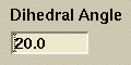
Used to specify the dihedral angle threshold (in degrees) used for feature identification. The dihedral angle is the angle between adjacent boundary faces. Edges with dihedral angles greater than the specified threshold will be considered candidate features. The dihedral angle threshold can be specified via the command line using either the -dihedralangle or -da options. The dihedral angle threshold is used only if the feature identification toggle is turned on.
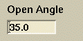
Used to specify the open angle threshold (in degrees) used for feature identification. The open
angle threshold is used to identify corners. Those having an open angle greater than the specified
threshold will be considered candidate features. The open angle threshold can be specified via the
command line using either the -openangle or -oa
options. The open angle threshold is used only if the feature identification
toggle is turned on.
CAPRI options

Specify the machine running the CAPRI server.

Specify the port number for the CAPRI server communication.
Specify whether the CAPRI server uses a secure connection.

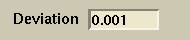
Specify the maximum angle (in Degrees) between triangle neighbors. Any two adjacent triangles with an angle greater than the specified value will be broken up if possible.

Specify the fraction of the min-max box diagonal of the model volume to set the maximum triangle side length. Any triangle with sides greater than this value will be split up if not on an Edge.
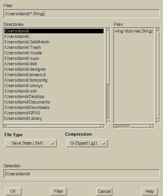
In the SM Write File Window, there are four fields. The Directories field allows you to browse through directories and select the desired directory. The Filter field displays the choice and the file extensions currently being used in the search. The Files field will display the files in that directory that match the current filter selection. The file filter selection can be updated by either changing the file type selector or typing in the Filter field and clicking the Filter button. To select a file to write, either click the file name listed in the Files field and the file name will be displayed in the Selection field or simply type the filename in the Selection field. The OK button writes the file listed in the Selection field. The Cancel button does not write the file and returns back to SolidMesh.
The File types menu is used to determine the type of information written by
SolidMesh. Valid output types are
IGES and a variety of grid file types.
IGES, XYZ, and
surface grid files
can be written out with bzip2, gzip, compress, or with no file compression of any kind. There are
nine file types that can be written by
SolidMesh:
- Save State: .SM
- IGES: .igs
- XYZ: .xyz
- Note that only the parametric curves are written to
XYZ files.
- Surface grid: .surf
- UGRID volume Grid: .ugrid
- NASTRAN volume grid: .nas
- CGNS volume grid: .cgns
- CFD++ volume grid: .cfd++
- Three files are generated for CFD++
formatted grids:
- nodesin.bin: coordinate information
- cellsin.bin: element/cell connectivity
- exbcsin.bin: external boundary condition or grid groups
- Cobalt volume grid: .cobalt.grd
- FieldView volume grid: .fvuns
- Fluent volume grid: .fluent.cas
- NSU3D volume grid: .mcell
- VGRID volume grid: .cogsg
- Cart3D surface triangulation (Tri file): .tri
- Stereolithography: .stl
- OpenFOAM polyMesh volume grid: .foam
- Five files are generated for OpenFOAM polyMesh
formatted grids:
- points: coordinate information
- faces: face information (defined by points)
- owner: cell owner file (cells defined by faces)
- boundary: boundary face definition
- neighbor: face neighbor definition
Compression types:
- Compressed: .Z
- G-zipped: .gz
- bzipped: .bz2
- No compression: No file extension
Format Specifications:
UGRID,
Plot3D, and
FGRID/UFast grid files may include the following format specifications:
- unformatted single precision: .r4
- unformatted double precision: .r8
- binary single precision: .b4
- binary double precision: .b8
- ascii (formatted): No file extension

For certain CAD systems to read a SolidMesh IGES file, you must output parametric space curve definitions. This option should only be specified (blackened radio button) for these CAD systems. Outputting parametric space curve definitions may double the size of the output file. This option is valid only for IGES files and cannot be combined with the Output Parametric Curves as Physical Curves option.

Writes parametric curves as physical curves. This is useful when extracting curves for the 2D version of SolidMesh. This option is valid only for IGES files and cannot be combined with the Output Parametric Curves Space Curves option.

For surface meshes, writes the normal vector for each node of the triangle or quadrilateral elements. The normal is evaluated based on the underlying geometric surface. The face normal information is written to a file called casename.surfn. The format of the file is
Number_of_Surf_Triangles Number_of_Surf_Quads
Vx Vy Vz for node 1 of tria boundary face 1
Vx Vy Vz for node 2 of tria boundary face 1
Vx Vy Vz for node 3 of tria boundary face 1
Vx Vy Vz for node 1 of tria boundary face 2
Vx Vy Vz for node 2 of tria boundary face 2
Vx Vy Vz for node 3 of tria boundary face 2
...
Vx Vy Vz for node 1 of tria boundary face Number_of_Surf_Triangles
Vx Vy Vz for node 2 of tria boundary face Number_of_Surf_Triangles
Vx Vy Vz for node 3 of tria boundary face Number_of_Surf_Triangles
Vx Vy Vz for node 1 of quad boundary face 1
Vx Vy Vz for node 2 of quad boundary face 1
Vx Vy Vz for node 3 of quad boundary face 1
Vx Vy Vz for node 4 of quad boundary face 1
Vx Vy Vz for node 1 of quad boundary face 2
Vx Vy Vz for node 2 of quad boundary face 2
Vx Vy Vz for node 3 of quad boundary face 2
Vx Vy Vz for node 4 of quad boundary face 2
...
Vx Vy Vz for node 1 of quad boundary face Number_of_Surf_Quads
Vx Vy Vz for node 2 of quad boundary face Number_of_Surf_Quads
Vx Vy Vz for node 3 of quad boundary face Number_of_Surf_Quads
Vx Vy Vz for node 4 of quad boundary face Number_of_Surf_Quads
 |
 |
 |
 |