


Discrete Geometry Interface
Discrete Geometry Topology Definition Interface
The discrete geometry graphical user interface (GUI) allows the user to manually define the topology. The feature detection algorithm identifies the features and topological boundaries in the model. The topology definition GUI allows the user to manually add or remove edges with minimal effort to further refine or define the topology. The command line option to disable the feature identification algorithm is -nofeatureid.
The edges are colored according to classification with the following precedence:
- Edges identified as features are colored yellow
- Boundary edges are colored green
- Surface patch boundaries (i.e. Group boundaries) are colored cyan
- User-added edges are colored blue
- Candidate edges are colored red
- Free-edges (i.e. edges that failed the topology check) are colored magenta
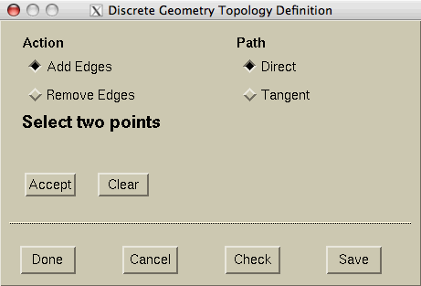
The discrete geometry topology definition GUI in Add Edge mode.
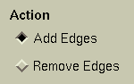
There are two selection options: Add Edges or Remove Edges. In the
Add Edge mode, all points and are candidate edges are
selectable. Selecting a candidate edge (a
red edge) will clear it. In
Remove Edge mode, only classified edges
are selectable.
If any candidate edges are selected when the
mode is changed, the user will be prompted as to keep
or discard the candidate edges or
cancel the request to change selection modes.
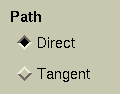
There are two options to add edges: Direct and Tangent.
With the Direct path option, two points must be selected. The first point defines
the starting location and the second point is the ending location. These two points also
define a direction vector starting from the 1st point and heading to the 2nd point. The
edges most aligned with the direction vector are selected.
With the Tangent path option, three points must be selected.
The first point defines the starting location,
the second point defines the start or tangent direction, and
the third point is the end location.
The edges are selected so that the angle between adjacent edges is minimized. This is
useful for selecting smooth feature lines in the model that were missed by the
automated feature detection algorithm.
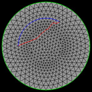
An example of the two methods is shown in the figure below. The same starting and ending points were used for each method and the edges selected by the
Direct Path are shown in
red and the edges selected by the
Tangent Path are shown in
blue.
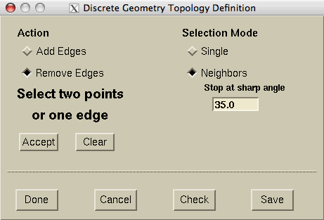
The discrete geometry topology definition GUI in Remove Edge mode. In the Remove Edge mode, only edges that have been selected by either the automated or manual methods (i.e. classified edges), can be selected for removed from the topology definition. Points on the classified edges are also selectable.
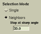
There are two edge selection modes: Single and Neighbors. In the Single mode, individual edges can be selected for fine control. In the Neighbors mode, edges adjacent to the selected edge are selected if the angle between them is less than the specified angle. Adjacent edges are chained together and continually added until the angle criteria is no longer satisfied. In either mode, two points may be selected and all the classified edges between the two points are selected.


Discard the candidate edges.

End the topology definition and process the discrete geometry. If any candidate edges are selected when the Done button is selected, the user will be prompted as to process or discard the candidate edges or cancel the request.

Remove all user-defined edges from the topology definition and process the discrete geometry.

Perform an edge topology check and identify free edges. Free edges are edges that do not form a closed loop. When the discrete geometry is processed, all free edges are discarded and thus some features may be lost if they do not form a closed loop.

Save the topology definition, i.e. the edge classification, toa file called casename.dgt. This file can be used for restart purposes.&npsb; The command line option to restart using the topology definition is -dgrestart.
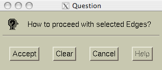
If any candidate edges are selected when the Selection Mode is changed or the user finishes the topology defintion, the user will be prompted as to keep or discard the candidate edges or cancel the action.
Accept the candidate edges and process the action.
Discard the candidate edges and process the action.
Keep the candidate edges and cancel the action request.
 |
 |
 |
 |