


Tutorials: CAD Clean-up
Often the most time consuming step in the unstructured grid generation process is geometry clean-up. A lot of times, the geometry to be modeled was originally built in another CAD system and read into SolidMesh from an IGES file. Usually, when the geometry was not constructed in SolidMesh (and sometimes when it is if care was not taken during construction), CAD clean-up is required before a grid can be generated. This tutorial is intended to illustrate a few techniques used to clean up a CAD file. It should be noted that any geometry problem could be fixed any number of ways depending on the situation. Also, since CAD clean-up changes the geometry, some techniques may not be appropriate where retaining the original geometry is crucial. The end result is to obtain a topologically valid (water tight) model free of any holes, overlaps, surface mismatches, ... Geometry problems covered in this tutorial include: nonintersecting surfaces, overlapping surfaces, badly parameterized surfaces, and surfaces that don't meet at a single point. Selecting and adjusting the glue tolerance is included as well. Also, techniques using group activation and deactivation when dealing with surfaces will also be illustrated. Start by downloading the IGES file: flying_minnow.igs.gz. REMINDER: This tutorial is rather long. It is a good idea to save periodically. Also, if you do have to stop and later read in an intermediate model, when you restart, read the file in with no gluing (-ng).
1. Read flying_minnow.igs.gz
into SolidMesh (shown with surfaces shaded) with trimming and gluing
enabled (see  for help). The surfaces of the model will initially be drawn
as wireframe. The surfaces shown to the right are drawn as shaded.
Throughout the tutorial the pictures may switch between either for viewing
clarity.
for help). The surfaces of the model will initially be drawn
as wireframe. The surfaces shown to the right are drawn as shaded.
Throughout the tutorial the pictures may switch between either for viewing
clarity.
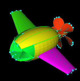
2. To start, hit  to find problem areas.
will highlight problems by selecting every curve that is not adjacent to
exactly two surfaces. Some of these can be fixed by creating trimmed surfaces but others will
require a little more work. Clear the pick list by hitting "Esc".
to find problem areas.
will highlight problems by selecting every curve that is not adjacent to
exactly two surfaces. Some of these can be fixed by creating trimmed surfaces but others will
require a little more work. Clear the pick list by hitting "Esc".
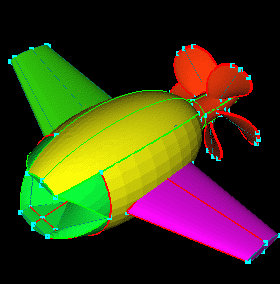
3. The first clean-up step is
to decide if the glue tolerance can be raised
to allow gluing of more of the curves. Determination of the glue
tolerance is an ongoing process. Basically, you want to keep it as
small as reasonably possible. Find the smallest feature to be retained
and/or try to estimate what the smallest spacing applied to the surface
grid will be and make sure the tolerance doesn't go above about an order
of magnitude smaller. For this case, the propeller will probably
require the tightest spacings. To estimate the spacing that will
be required, select the points shown and  .
The message window reports the distance between the two points is 0.867665.
A good estimate of the spacing required is around 0.03 or 0.04. This
means the glue tolerance shouldn't exceed about 0.004. This is just
a ballpark maximum for reference. Don't actually change the glue
tolerance right now.
NOTE: The point spacing required is dependent on the geometry
and coming up with good estimates of point spacing and/or glue tolerance
comes with practice/experience.
.
The message window reports the distance between the two points is 0.867665.
A good estimate of the spacing required is around 0.03 or 0.04. This
means the glue tolerance shouldn't exceed about 0.004. This is just
a ballpark maximum for reference. Don't actually change the glue
tolerance right now.
NOTE: The point spacing required is dependent on the geometry
and coming up with good estimates of point spacing and/or glue tolerance
comes with practice/experience.
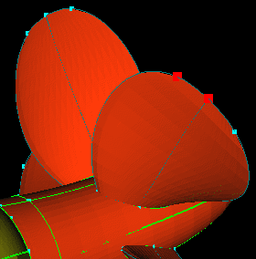
4. Hit "esc" to clear the pick list and
again. You can see most of the problems with the topology are around
the prop. Clear the pick list. Select the two curves (a derived
curve from each surface) shown (select twice in the location of the curve
shown in red) and  .
The message window reports:
Max Internal dist = 2.98372e-05
.
The message window reports:
Max Internal dist = 2.98372e-05
Max Vertex dist = 0
Since this is much smaller than the ballpark max from step 3, the glue
tolerance can be raised to include gluing these curves. A good new
tolerance would be one slightly larger than the Max Internal dist above.
Set the  (you have to hit enter in the tolerance field after you change the tolerance)
as shown and
(when gluing with nothing selected, all visible curves and vertices are
glued at the specified tolerance).
RULE OF THUMB: If you manually glue two curves and the Max Vertex
dist is relatively large (not 0 or close given the model scale), you may
not have selected the intended curves, or there may exist a more significant
problem.
(you have to hit enter in the tolerance field after you change the tolerance)
as shown and
(when gluing with nothing selected, all visible curves and vertices are
glued at the specified tolerance).
RULE OF THUMB: If you manually glue two curves and the Max Vertex
dist is relatively large (not 0 or close given the model scale), you may
not have selected the intended curves, or there may exist a more significant
problem.
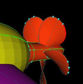
5.
again. You can see most of the prop curves got glued, but there are
still a few problems.
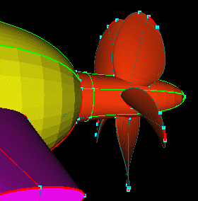
6. Hit "esc" to clear the pick list. Like step 3, select
the curves shown (again, you will have to pick twice in the same place
to get both curves) and .
Check the message window:
Max Internal dist = 5.25802e-05
Max Vertex dist = 0
Since the Max Internal dist is still much smaller than the estimated
max, increase the glue tolerance to 8e-4.
and .
You can see this cleared up most of the problems with the prop. Hit
"esc" to clear the pick list.
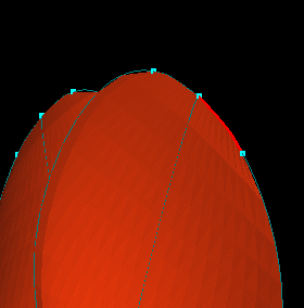
7. Most of the other problems will require trimming or CAD work,
so start with the Mouth. Select every group but Mouth and  .
This deactivates or removes all the other objects from the on and off scenes and allows
work to be done more easily on just the Mouth surfaces.
to see the problem areas, then clear the pick list.
.
This deactivates or removes all the other objects from the on and off scenes and allows
work to be done more easily on just the Mouth surfaces.
to see the problem areas, then clear the pick list.
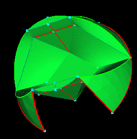
8. Starting with the top cross shaped curves, select the
point shown and  to make this point the new center of rotation.
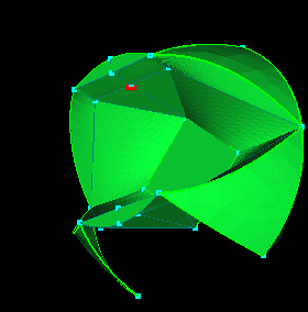
9. Zooming, you can see two of the surfaces overlap and two have a
large gap that can't simply be glued. To repair the surfaces, the
original geometry will be changed slightly. Care must be taken to
make the impact as small as possible. Select the four surfaces affected
and turn them  and
and  .
.
10. Inspection of the surface wireframe reveals some questionable surface
parameterization, identified by the skewed wireframe. Since the surfaces
in question are mostly planar with little to no internal curvature, a single
carpeted surface can be created to close the gap and eliminate the overlap.
Select all four surfaces and  to increase the display resolution for a better projection.
NOTE: Carpeting is not the only way to fix this problem. You could
try splitting the surfaces up, getting rid of the extra, and unioning them
back together, but this will not solve the parameterization problem.
Experimentation is the best way to learn clean-up techniques.
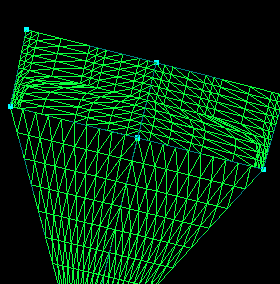
11. Select the two curves shown and  .
This will create a physical (yellow) curve.
.
This will create a physical (yellow) curve.
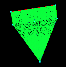
12. Zoom on the lower, outside corner of one of the rectangular surfaces. You can see another gap here. A decision must now be made about which curve to keep. The curve which best represents the shape of the geometry should be kept. This requires a judgment call. For this example, the straight curve will be discarded.
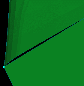
13. A curve like the one created in step 11 needs to be created between
the rectangular surfaces and the triangular surfaces. Because of
the overlap seen in step 9, the curves can not simply be unioned as in
step 11. For now, select the two triangular surfaces and turn them
off. Zoom in on the same area as in step 9. Select the curve
and point shown and  .
It doesn't really matter which curve or point is selected as long as the
result is similar to the picture at the right. Basically, you want
to create two curves that meet at a single point by splitting off the end
of one of the curves at the appropriate point.
.
It doesn't really matter which curve or point is selected as long as the
result is similar to the picture at the right. Basically, you want
to create two curves that meet at a single point by splitting off the end
of one of the curves at the appropriate point.
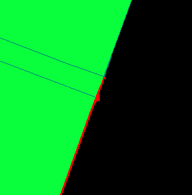
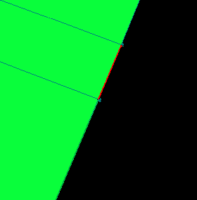
14. Hit "r" to change the Pick Limit to Parametric
and select the small curve between the two points.
You may have difficulty picking while zoomed in real tight. You may
have to adjust the clipping plane using the "page-down" and "page-up" buttons
to move it back or forward.  the selected curve.
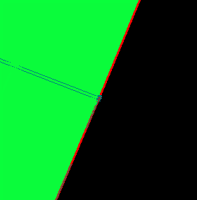
15. Keeping the Pick Limit set to Parametric,
select the remaining portion
of the curve split in step 13. Hit "c" and select the bounding curve
of the other surfaces as shown. The curves should meet at the point
used to split in step 13. Click .
Now you should have two yellow (physical) curves running the length of
the long sides of the surfaces.
16. Select the curves shown using the pick limit set to "physical" while picking the long curves and "curve" while picking the short sides.
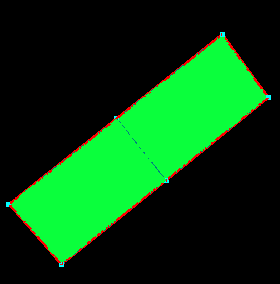
17. Select the surfaces so the new carpet will be projected onto
the old surfaces. Change the Long Res
field to 35 and the Short Res field
to 21 and  .
A new surface is created using 35X21 control points and projected onto
the old ones. This fixes the overlap problem and the parameterization
problem.
.
A new surface is created using 35X21 control points and projected onto
the old ones. This fixes the overlap problem and the parameterization
problem.
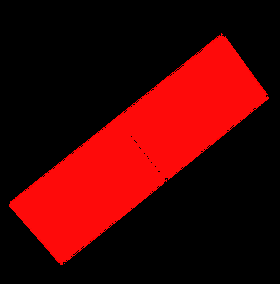
18. Select the old surfaces and the curves created in steps 13
and 15 (the physical curves) and .
Also, ,
select the triangular surfaces shown. Click
and .
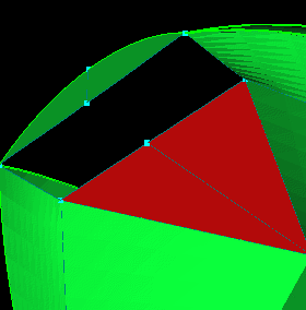
19. Zooming on the corner of the rectangular surface where it
meets the triangular surface, you can see there is still a gap between
the new surface and the triangular surfaces. In cases like this,
it is helpful to know how the surfaces to be repaired were generated to
know if there is internal curvature in the surface that needs to be retained.
In this case, the triangular surfaces were created using  so there is no internal curvature. Inspection of the surface also
indicates this is true. So, the surfaces can be repaired by creating
a new TFI surface. If you don't know how a surface or group of surfaces
was generated, you just have to do your best to determine which features
are most important and which can be "approximated."
so there is no internal curvature. Inspection of the surface also
indicates this is true. So, the surfaces can be repaired by creating
a new TFI surface. If you don't know how a surface or group of surfaces
was generated, you just have to do your best to determine which features
are most important and which can be "approximated."
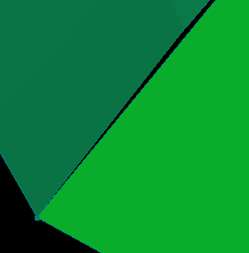
20. Select the three curves and point shown. Be careful
when selecting the curve between the two surfaces not to select one of
the shorter curves that runs only halfway across the bottom of the rectangular
surface. The curve across from the selected point is the bounding curve
from the new surface created in step 17. Click
to create the new surface.
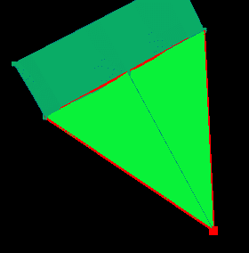
21. Select the green surfaces and
.
Then, select the two remaining surfaces (the two new surfaces), click the
Mouth group name and  .
.
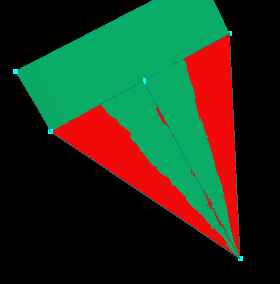
22. If you remember, the edge shown picked meets two surfaces
(that are turned off). The rectangular surface will have to be trimmed
so select it and  .
Select the curve shown. Remember to use pick limit set to "param" (hit
"r") when picking to ensure the correct curve is picked.
.
Select the curve shown. Remember to use pick limit set to "param" (hit
"r") when picking to ensure the correct curve is picked.
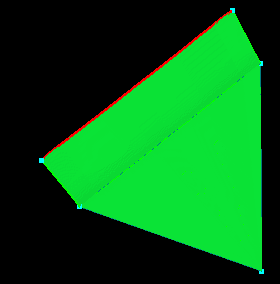
23. Click
, and select the point shown. The curve picked in the previous step
remains picked and visible when you toggle. Click
and
again.
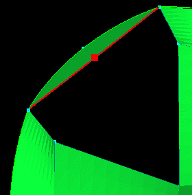
24. Select the rectangular surface and  (surfaces shown as wireframe surfaces).
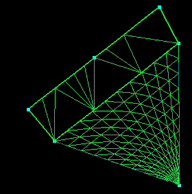
25. Click  .
then
to see if the problem was fixed. As you can see, the overlapping
and gap problems are gone because the surfaces have been replaced, but
creating the carpet has caused new problems with the surfaces above it.
This is because the value used in step 17 when creating the carpet was
too small to resolve the edge enough so that it would glue to the surfaces
above it with the current tolerance. Increase the glue tolerance
to 0.0035 and
then .
Another way to fix this problem, if the tolerance could not be increased,
would be to rebuild the indicated surfaces, or if the indicated surfaces
had internal curvature and could not be easily rebuilt, you could try returning
to step 17 and using a value larger than 35 when carpeting.
Hit "esc" to clear the pick list.
.
then
to see if the problem was fixed. As you can see, the overlapping
and gap problems are gone because the surfaces have been replaced, but
creating the carpet has caused new problems with the surfaces above it.
This is because the value used in step 17 when creating the carpet was
too small to resolve the edge enough so that it would glue to the surfaces
above it with the current tolerance. Increase the glue tolerance
to 0.0035 and
then .
Another way to fix this problem, if the tolerance could not be increased,
would be to rebuild the indicated surfaces, or if the indicated surfaces
had internal curvature and could not be easily rebuilt, you could try returning
to step 17 and using a value larger than 35 when carpeting.
Hit "esc" to clear the pick list.
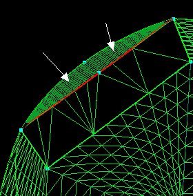
26. Select the surfaces opposite those repaired. These
surfaces are simply a mirror of the ones just repaired, so there is no
need to repeat steps 9 through 26.
the selected surfaces.
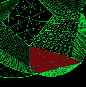
27. Select the cleaned-up surfaces shown.
Define the plane to be mirrored about by changing the values in the VX, VY, and VZ fields to
 .
No point needs to be selected since the mirror is about the origin (the
default). Click
.
No point needs to be selected since the mirror is about the origin (the
default). Click  (in the Util panel). This should replace the surfaces you just deleted
with the ones you just repaired.
then
to see any problems. The only curves selected are on the boundary.
We will need the adjacent surfaces to determine if there is a problem there.
(in the Util panel). This should replace the surfaces you just deleted
with the ones you just repaired.
then
to see any problems. The only curves selected are on the boundary.
We will need the adjacent surfaces to determine if there is a problem there.
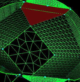
28. Select the Body and RightWing groups and  .
You can see the problems on the boundary of the Mouth are because some
of the Body surfaces need to be trimmed. The Mouth is finished for
now, so select the Mouth group and .
Select the RightWing group and the Body surface shown and increase the
display
resolution to 41x41. This is needed to get a good intersection of the
wing and body.
.
You can see the problems on the boundary of the Mouth are because some
of the Body surfaces need to be trimmed. The Mouth is finished for
now, so select the Mouth group and .
Select the RightWing group and the Body surface shown and increase the
display
resolution to 41x41. This is needed to get a good intersection of the
wing and body.
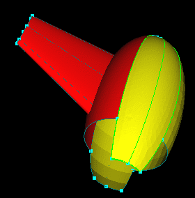
29. We now need to trim the Body surface to remove the portion
inside the RightWing and make it connect properly to its neighbors.
Select the Body surface shown above and just the RightWing surfaces that
intersect the Body surface. The surfaces should be picked in that
order (Body surface first, then RightWing surfaces) so that the intersection
is done properly. Click  .
This creates curves at the intersection of the body and wing which will
be used for trimming. For now, click the RightWing group and .
Also, click the Prop and Mouth groups and .
.
This creates curves at the intersection of the body and wing which will
be used for trimming. For now, click the RightWing group and .
Also, click the Prop and Mouth groups and .
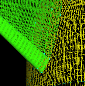
30. Select the surface shown (the one you just did the intersection
with) and click
and .
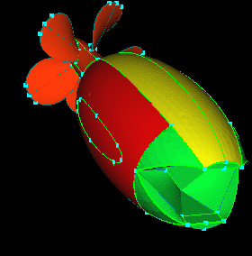
31. Re-select the surface and .
Select the curve shown (the longer of the two short sides) and .
Be sure when selecting the curve to have the pick limit set to "Param"
so you get the correct curve.
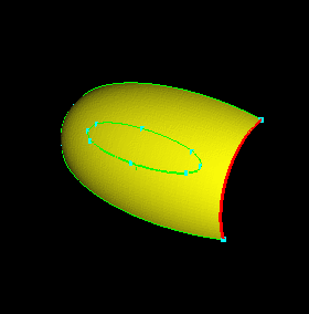
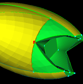
32. Select the point shown and
and .
33. Select the curve shown (opposite the one just split) and .
Again, use "Parametric" when picking.
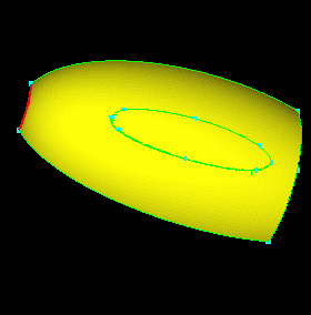
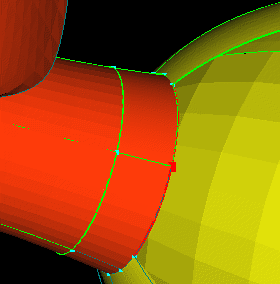
34. Select the point shown,
and .
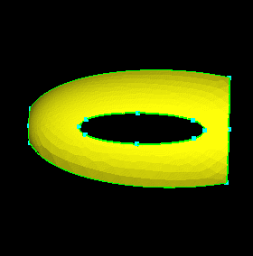
35. Select the surface and .
This redefines the surface using two trimming loops of parametric curves,
one on the interior created by intersecting with the RightWing and one
at the boundary created by extracting the bounding curves and splitting.
The bounding curves were split in steps 32 and 34 so that once glued the
surface to the right will be adjacent to it's neighbors, assuming the resulting
segments are within tolerance.
36. Click
and select the surface shown (the surface picked is untrimmed, you can
tell by looking at the wireframe, also, it's the one on the side with the
surface just trimmed in the previous step). Turn it
and .
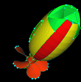
37.  and .
Then, select the curve shown (the shortest of the short side) and .
Be sure to set the pick limit to "Parametric" before picking.
and .
Then, select the curve shown (the shortest of the short side) and .
Be sure to set the pick limit to "Parametric" before picking.
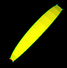
38. Select the point shown,
and .
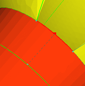
39. Using "Param", select the curve shown and .
(The picked curve is the one neighboring the Mouth as seen in the next
step).
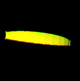
40. Select the point shown,
and .
Select the surface and .
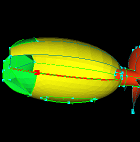
41. Click ,
select the surface shown (the one beside the surface trimmed in the previous
step), and .
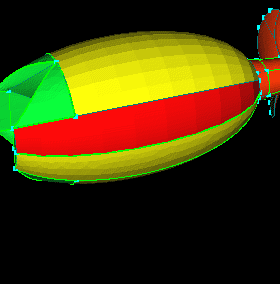
42. Hit "r" and select the curve shown. Be sure to position
the cursor over the curve to the right of the point shown picked.
This will ensure the correct curve is picked. You can know the parametric
being picked is the one extracted in the previous step because no others
lie under the selected curve (if you have been following along, keeping
your geometry clean). There should have been no other green curves
to the right of the selected point before you extracted those from the
surface in step 41. Keeping a clean geometry is key to knowing what
you have picked.
Select the point shown and.
Select the same surface as in step 41 and .
NOTE: The last two surfaces were trimmed so that their boundaries
will meet their neighbors' boundaries properly and be adjacent when glued.
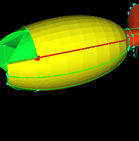
43. Moving to the wings, click the Prop, Mouth, and Body groups
and .
Click the RightWing group and .
As you can see, the portion left of the curves created in step 28 needs
to be trimmed off, select the surface shown and .
It doesn't really matter which surface you pick as long as it's one of
the 8 surfaces running from the body to the wing tip. The procedure
for one is the same as for the others.
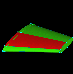
44. Select the curve (using Parametric) and point shown and .
Repeat for the curve on the opposite side of the same surface.
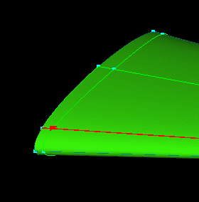
45. Select the parametrics shown (using Parametric) and
.
Then select the surface and .
Select the surface you just trimmed and click
then  .
The Child button removes the children of surfaces that are not visible
and turns on children of surfaces that are visible. This helps to
make sure the parametrics (green curves) you see are those associated with
the surfaces you see.
Repeat the procedure in steps 43 through 45 for the other surfaces.
This finishes the work on the RightWing surfaces.
.
The Child button removes the children of surfaces that are not visible
and turns on children of surfaces that are visible. This helps to
make sure the parametrics (green curves) you see are those associated with
the surfaces you see.
Repeat the procedure in steps 43 through 45 for the other surfaces.
This finishes the work on the RightWing surfaces.
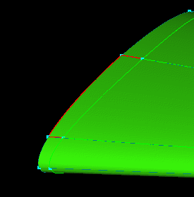
46.
all groups,
then
to see what problems remain. As you can see, a few problems still exist
around the LeftWing and the Prop. Clear the pick list.
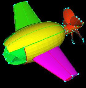
47. To finish the Prop area, click the Mouth, LeftWing,
and RightWing groups and .
A few of the surfaces where the prop meets the body still need trimming.
Select the surfaces shown (shown solid, in red) and
and .
(one of the surfaces picked is at the base of the surfaces trimmed for
the RightWing. the other is just above that, if the model is oriented with
the trimmed surface mentioned in the front, closest to you).
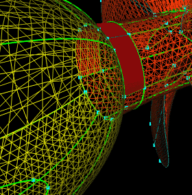
48. Hit "e" to change the pick type to "Everything," and pick
all curves. Click . You can see that the parametrics attached to the untrimmed surfaces
were only glued; they didn't "belong" to them. Hit "3" to change
the pick type back to 3D.
. You can see that the parametrics attached to the untrimmed surfaces
were only glued; they didn't "belong" to them. Hit "3" to change
the pick type back to 3D.
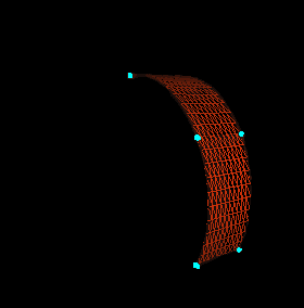
49. Select the two surfaces and .
Select the parametric shown (the curve picked is the one at the base of
the Body surface trimmed to meet the RightWing, see the next picture for
further clarification, the selected curve is indicated with the lower arrow)
and .
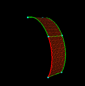
50. Select the point shown (indicated by the upper arrow) and .
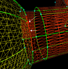
51. ,
select the surface and .
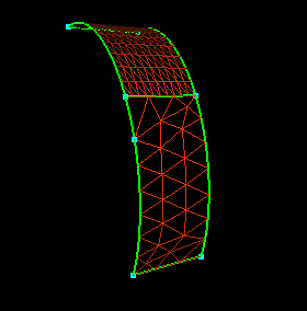
52. Select the parametric shown and .
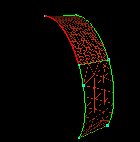
53. Select the 2 points shown and .
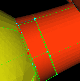
54. ,
select the surfaces and .
This should clear up the problems at the base of the body except for one
which will be cleared up later. Click .
NOTE: The two surfaces to the right were trimmed to create the
proper connectivity between them and their neighboring surfaces.
For either surface, splitting the parametrics at its boundaries has created
a 1 to 1 relationship between the segments at its boundaries and the corresponding
segments at its neighbor's boundaries.
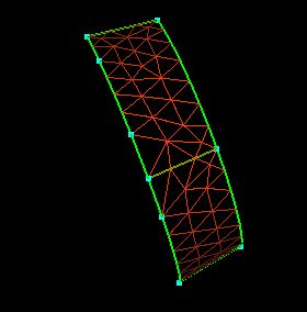
55. The only other problems with the prop were around the base
of the prop blades. This is because the surfaces below the blades
need trimming. In this case, the necessary parametrics have already
been provided. Select the surfaces shown (the easiest way is to hit
"p", position the cursor at the nose of the hub, behind the blades,
and right click. You should get 5 surfaces, one below each blade) and .
Click the Prop group and .
Click the LeftWing group and .
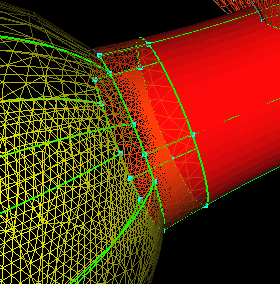
56. Close inspection of the wing tip reveals that one of the surfaces on the leading edge has a sliver of a surface that makes up the last piece. The surrounding surfaces could be trimmed to connect to these small surfaces, but depending on the spacing this could cause problems in the surface grid. It would be better if this was one surface. The best way to fix this problem would be to union the two surfaces. If this doesn't work a carpet could be created like before.
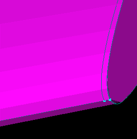
57. Select the two surfaces shown and .
Select the new surface, click on the LeftWing group and .
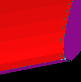
58. Looking at the underside of the wing, you can see another problem. This could be fixed in a number of ways. Again, the surfaces could be trimmed to create proper connectivity but this could cause problems in the surface grid. You could union the respective surfaces (or carpet if necessary). If the surfaces were intended to be split at this location, one of the two groups can be split and unioned so that all four surfaces meet at one corner.
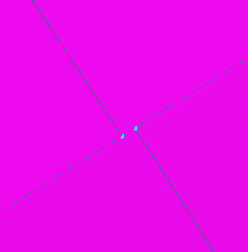
59. Select the surface and point shown. It shouldn't matter
which surface and point is selected, but to select the ones shown in the figure,
orient the model so that the top curve leads to the Leading Edge, and the lower
curves leads to the Trailing Edge of the wing. Click .
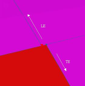
60. Select the surfaces shown and
. Select the new surfaces, click on the LeftWing group and .
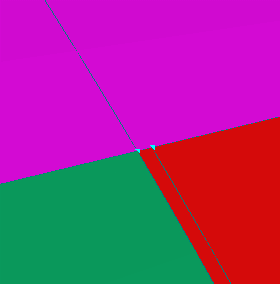
61. Select the point and surface shown (the point selected is
at the leading edge of the wing) and .
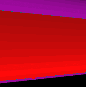
62. Move to the end of the curve created by splitting the surface
in the previous step. Select the point and surface shown and .
Select the four new surfaces, click the LeftWing group, and .
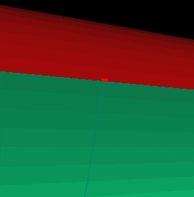
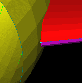
63. The last problem with the LeftWing surfaces is that they don't lie on or intersect the body. (The picture at the right is looking at the Leading Edge of the wing close to the body) To correct this the wing surfaces can be extended so that they intersect the Body at every point along the wing.
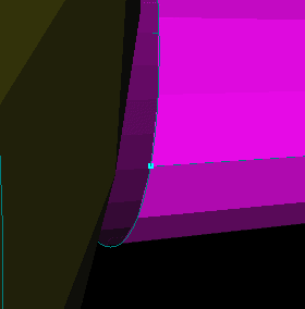
64. Select the surface and its bounding curve shown. (Leading
Edge, upper surface) Change the value in the  field (distance field in the CAD: Surf panel) to 0.25 and
  .
Repeat for the other 4 wing surfaces that should intersect the body (the
surfaces at the Trailing Edge should be extended also even though they
may look like they barely intersect already). The result should look
like the picture in the next step.
NOTE: Extending surfaces can slightly change the interior of the
surface depending on how much a given surface is extended. Also,
extending can potentially introduce problems with the surface parameterization.
This problem could be fixed a number of different ways; extending is just
the quickest. Again, the method of repair should be chosen after
considering the overall impact on the geometry of each possible method.
.
Repeat for the other 4 wing surfaces that should intersect the body (the
surfaces at the Trailing Edge should be extended also even though they
may look like they barely intersect already). The result should look
like the picture in the next step.
NOTE: Extending surfaces can slightly change the interior of the
surface depending on how much a given surface is extended. Also,
extending can potentially introduce problems with the surface parameterization.
This problem could be fixed a number of different ways; extending is just
the quickest. Again, the method of repair should be chosen after
considering the overall impact on the geometry of each possible method.
65. Select the old surfaces and
.
Select the new surfaces, click the LeftWing group, and.
The surfaces can now be intersected with the body and trimmed like the
RightWing.
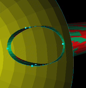
66. Select the surfaces shown and increase the display
resolution to 41x41. Select the body surface then all of the
intersecting surfaces (again the order picked is important to obtain the
proper intersection) and .
the Body group.
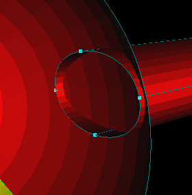
67. The surfaces need only to be trimmed. The same procedure
as in steps 43 - 46 could be used but another technique is used for illustration.
Select the surfaces shown, ,
and .
the surfaces and.
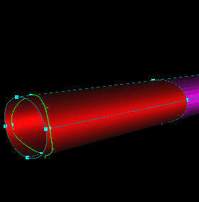
68. Hit "r" to set the pick limit to "Param." Position
the cursor over the curve shown selected. Pick twice to get both
parametrics (one from each surface). Pick the point shown and .
Repeat for the other three sets of curves around the wing. Don't
forget to use Pick Limit: Point when picking the split points.
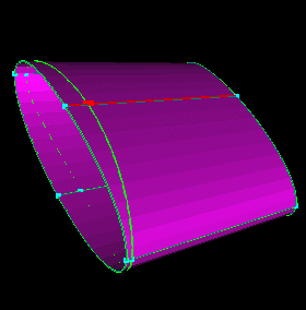
69. Remove the curves shown. Again, there are two curves below the split point, one from each surface. (there should be no green (parametric) curves left where red is shown).
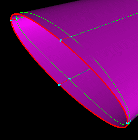
70. Select the surfaces and .
all groups and click
to be sure everything is visible.
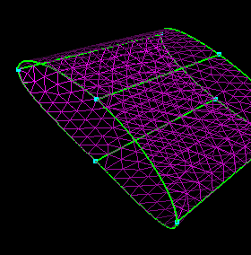
71. To clear up the final problems, select the surface shown.
and .
the surface and.
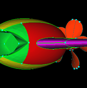
72. Select the parametric curve shown and .
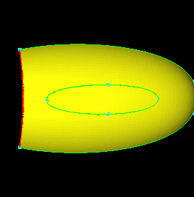
73. Select the point (remember to set the pick limit to "Point"
when picking points) shown
and .
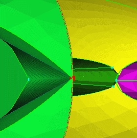
74. Select the parametric shown and .
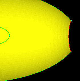
75. Select the two points shown
and .
Pick the surface and .
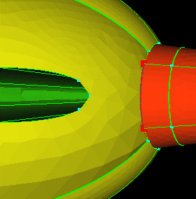
76. Click , ,
and .
You should get a message:
Integrity check passed!
0 Edges Picked
The CAD cleanup is done! Save your work for the next tutorial.
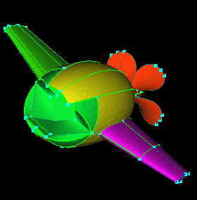
The model is now ready to have point spacings applied. The next tutorial covers splitting surfaces (like the prop and wing surfaces) to use points efficiently .
 |
 |
 |
 |