


Tutorials: Topology Tutorial - Trimming
The purpose of trimming is to create a topologically valid
geometry for surface grid generation. Trimming is used to give the
grid generator connectivity (or adjacency) between the geometric surfaces
of the model. Trimming is one tool for creating an "air-tight" (topologically
valid) model. Trimming basically redefines the boundaries of a surface
using loops of parametric curves of that surface.
Trimming Techniques 1 and 2 show two different ways to accomplish the
same objective. Trimming Technique 3 shows another use of trimming.
Trimming Technique 1
1. To start, read surfs.igs.gz
(right click on the filename and Save As) into SolidMesh (for help see
 ). For the group of surfaces shown to the right to be topologically
valid, the brown surface needs to be trimmed so that it connects to the
other two surfaces. Even this simple case can be used to illustrate
a couple trimming techniques.
). For the group of surfaces shown to the right to be topologically
valid, the brown surface needs to be trimmed so that it connects to the
other two surfaces. Even this simple case can be used to illustrate
a couple trimming techniques.
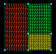
2. Select the brown surface and
 .
This extracts the boundaries of the surface.
.
This extracts the boundaries of the surface.
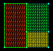
3. Set the pick limit to
 and pick the curve shown. Also use the hotkey
"p" to change the pick limit to point and select the point shown.
The parametric can be picked by setting the pick limit to curve but, the
boundary (derived curve) of the brown surface lies on top of the parametric
you want to pick. If you don't set the pick limit to param, you might
pick and split the wrong curve causing more problems with the topology.
One of the most important things to remember when trimming is to be sure
you are working with the curve you think you are. You can do this
by using pick limits and toggling the surfaces you want to work with on
and off.
and pick the curve shown. Also use the hotkey
"p" to change the pick limit to point and select the point shown.
The parametric can be picked by setting the pick limit to curve but, the
boundary (derived curve) of the brown surface lies on top of the parametric
you want to pick. If you don't set the pick limit to param, you might
pick and split the wrong curve causing more problems with the topology.
One of the most important things to remember when trimming is to be sure
you are working with the curve you think you are. You can do this
by using pick limits and toggling the surfaces you want to work with on
and off.
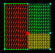
4. Click the split button,
 , to split the selected curve at the selected point. The surface is now
ready to trim.
, to split the selected curve at the selected point. The surface is now
ready to trim.
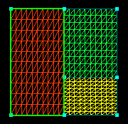
5. Select the brown surface and
 .
This "re-defines" the boundaries of the brown surface with the green parametric
curves. This creates valid connectivity between the three surfaces.
This would also be a good time to glue, so hit "esc" to clear the pick
list, and then, click
.
This "re-defines" the boundaries of the brown surface with the green parametric
curves. This creates valid connectivity between the three surfaces.
This would also be a good time to glue, so hit "esc" to clear the pick
list, and then, click
 .
A surface grid can now be generated.
.
A surface grid can now be generated.
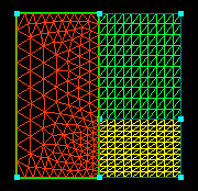
6. Hit "e" to set
 .
Use the left mouse button to select all of the points.
.
Use the left mouse button to select all of the points.
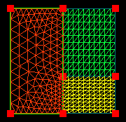
7. Click
 to go to the surface grid generation application. Enter a value for
 (a value between 0.1 and 0.5 would be a good choice, 0.25 for illustration)
and
(a value between 0.1 and 0.5 would be a good choice, 0.25 for illustration)
and  .
.
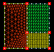
8. Now
 .
Toggle
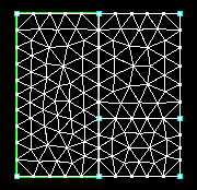
the surfaces off to see only the surface grid generated.
.
Toggle
the surfaces off to see only the surface grid generated.
Trimming Technique 2
1. To illustrate another method of trimming, restart SolidMesh and read the original surfs.igs.gz file in again.
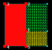
2. Select the points around the brown surface in the sequence shown and then select the surface. REMINDER: When picking a point (vertex), make sure the pick limit is set to POINT to be sure only vertices are selected and not interior points on the curve or surface. This will save time and sanity later.
3. Click  .
This creates four parametric curves associated with the brown surface.
NOTE: You might think of this as creating four physical curves and projecting
them on to the selected surface all in one step.
.
This creates four parametric curves associated with the brown surface.
NOTE: You might think of this as creating four physical curves and projecting
them on to the selected surface all in one step.
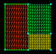
4. Complete the loop by picking the two remaining points and
the surface, and click
to create the remaining parametric needed. As you can see, the result
is identical to step 4 of the previous technique. The surface is
now ready for trimming and surface grid generation (steps 5 -8 of technique
1). This technique may be faster in some cases and there is no danger
of splitting the wrong curve like with the first technique, but with some
surfaces, particularly those with a lot of curvature at the boundaries,
the projection of the curve may not stay on the boundaries but extend into
the interior of the surface. This quirk of the projection routine
can make it necessary to create the needed curve by another method, like
the first technique shown.
Often surfaces required to model a given geometry are not simple geometric shapes, but ones with curved boundaries or interior complexities. Trimming can also be used as "cookie cutter" of sorts to remove or create more complex surfaces, as shown below. Continue with the results of either trimming technique.
Other Trimming
1. Continue from above, after trimming the brown surface.
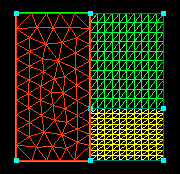
2. Suppose a cylindrical shaped surface intersects the yellow
surface perpendicularly. Read (append) the new surface in from an
additional file: cylinder.igs.gz.
(for more info on fileio see .)
Suppose the cylinder should extend from the yellow surface but not through
(like a pin fin on a flat plate). The shorter piece of the cylinder
that extends through the surface needs to be trimmed off and a circular
piece needs to be cut out of the yellow surface.
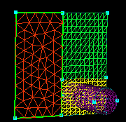
3. Select the yellow surface, then the two pieces of the cylinder
(in that order) and  .
This creates four new curves at the intersection of the cylinder and the
yellow surface (two on the yellow surface and one on each of the two cylinder
surfaces). This, in itself, is not enough to create the new trimmed
surfaces. The rest of the trimming loop must now be created.
.
This creates four new curves at the intersection of the cylinder and the
yellow surface (two on the yellow surface and one on each of the two cylinder
surfaces). This, in itself, is not enough to create the new trimmed
surfaces. The rest of the trimming loop must now be created.
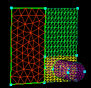
4. First, to create the trimmed cylinder, select the two cylinder
surfaces, turn them  ,
and
,
and  .
This makes it easier to work with the surfaces and on larger geometries
with lots of surfaces, speeds the picking.
.
This makes it easier to work with the surfaces and on larger geometries
with lots of surfaces, speeds the picking.
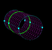
5. Select both surfaces and .
Where the surfaces share a common boundary, there will be two parametrics,
one associated with each surface.
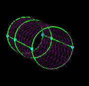
6. Select the point shown (use PICK LIMIT: POINT). Also, set the pick limit to PARAM and select both parametrics, but not the surface boundary (derived) curves (although the images to the left looks like only one curve is selected, two curves, one from each surface, at the same location are picked so you will have to pick twice). Split the curves. Do this for both sides. The result will look identical to the picture for step 5, but now the parametrics will be split at the middle point.
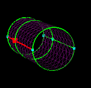
7. Since only the portion of the cylinder from the intersection
forward is wanted, the curves at the base should be deleted so the surfaces
will trim. One quick way is to hit "p" to set the pick limit to POINT,
position the pointer over one of the points at the base, and press the
middle mouse button. This selects all curves connected at this point.
This will select the bounding curves also, but they won't delete anyway
(so, don't worry about them). Once you have selected the curves at
both points,
 . The surfaces are now ready to trim.
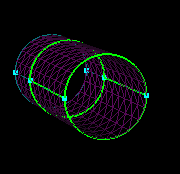
8. Select both surfaces and .
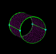
9. Now, the yellow surface needs to have the portion that would
be inside the cylinder trimmed out. Press
to return to the yellow surface leaving the cylinder turned off.
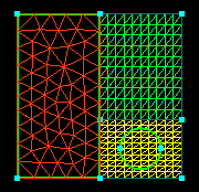
10. In order to keep the portion outside the cylinder and get
rid of only the portion inside the circle, select the surface and .
This creates two loops of parametrics, one composed of four curves around
the outer boundary and the second on the interior of the surface composed
of two semi-circles.
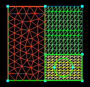
11. Select the surface and .
If you had not extracted the bounding curves, SolidMesh would have removed
the portion outside the cylinder leaving the portion inside the circle.
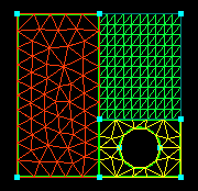
12. Hit  to return the trimmed cylinder to the visible scene. The surfaces
are now ready to grid.
to return the trimmed cylinder to the visible scene. The surfaces
are now ready to grid.
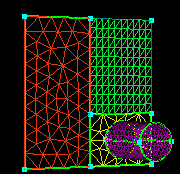
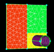
 |
 |
 |
 |