


Grid Utilities

Grid Utilities Applications
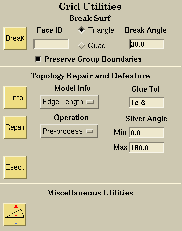
Break Surface

BreakSurf Utility
The BreakSurf utility is used to split or subdivided existing Groups based on discontinuities. A starting boundary face (either tria or quad) is specified in the Boundary Seed Face ID field and a new Group is generated. Beginning with the seed face, the algorithm proceeds by checking the dihedral angle between neighboring faces and adding those whose angle is less than the Break Angle to the new Group. Note that a new Group will be created containing at least the seed face. This function can also be invoked using the hotkey, Shift-b.
Specify the starting or seed boundary face (triangle or quad) id. The triangle faces are numbered 1 - ntriangles and the quads are numbered 1 - nquads. The element type is specified using the Boundary Face Topology chooser.
Specify the starting face topology type.
Specify the break or dihedral angle.

If this toggle is selected, BreakSurf will stop at and retain Group boundaries, regardless of the dihedral angle.
Topology Repair and Defeature
Generate "water-tight" discrete data by using various tools available in the GridRx library toolkit. A complete description of the operations can be found in the GridRx documentation.

Provides the global information indicated in the Model Info menu on the entire grid or for selected surfaces. This information can be used as a guide used to determine needed tolerances.
Choose to calculate global Edge Length minimum and maximum values or Feature Size values for the whole grid or selected components to help determine needed tolerance or parameter values. The reported bounds on the glue and resolution tolerances are based on the following:
- Glue Tolerance minimum value = Minimum distance between boundary nodes
- Glue Tolerance maximum value = Minimum boundary edge length
- Resolution Tolerance minimum value = Minimum boundary edge length
- Resolution Tolerance maximum value = Maximum boundary edge length

Repair the whole grid or selected components based on the option selected in the Operation menu.
Choose which option of GridRx to perform on the entire grid or selected surfaces.
- Pre-process: Performs pre-processing checks to insure the integrity of the input grid. Duplicate nodes and zero-area triangles are removed. The tolerance for the coincident node check is the Glue Tolerance and the zero-area triangle uses machine-zero as the tolerance. Optionally, sliver triangles can be removed by specifying the angle criteria.
- Stitch: The stitching operation can be used to remove discrepancies across boundary edges within the specified Resolution Tolerance. This operation can be used to process topological issues such as gaps, intersections, and overlaps and may change the geometry. Pairs of boundary vertices are merged and moved to a new location that is half way between the paired vertices.
- Fill: The fill operation adds triangles to fill gaps between surface patches that are within the specified Resolution Tolerance.
- Stitch & Fill: Use both the Stitch operation and the Fill operation to remove edge discrepancies. Any gaps, overlaps, etc., within the Glue Tolerance will be stitched and any that are between the Glue Tolerance and the Resolution Tolerance will be filled.
- Defeature: Removes surfaces that are smaller than the specified feature size value.

Supply the glue tolerance to use for Stitch and Fill operation. The value should not be larger than the Resolution Tolerance. The glue tolerance is also used to specify the coincident node tolerance for the Pre-processing operation.
Supply the resolution tolerance to use to operate on the grid during the operations of Fill, Stitch, Stich & Fill, and EdgeCollapse. The value should not be larger than the determined search tolerance. Setting this value larger than the largest edge length could cause a boundary vertex to be paired with two vertices instead of one. Use the Info button to determine appropriate values.
Indicate if a global or local tolerance is specified. The use of a locally-varying resolution tolerance can help preserve small features in the model. The local tolerance is defined as a percentage of the longest edge length attached to a boundary node as the resolution tolerance for that node only. Specify the percentage in the Resolution Tolerance textfield. If a local Resolution Tolerance is used, the Glue Tolerance should be specified as a percentage of the Resolution Tolerance.
These fields are used to specify the angle criteria used by the Pre-processing operation to remove sliver triangles. Triangles having an angle less than the Min Angle or greater than the Max Angle will be removed.

This grid tool will intersect two unstructured surface patches. These surface patches must be two-manifold and non self-intersecting. The result from using this tool will necessarily be a non-manifold mesh that has been split into new groups based on the intersection present in the mesh. Consider the following example:
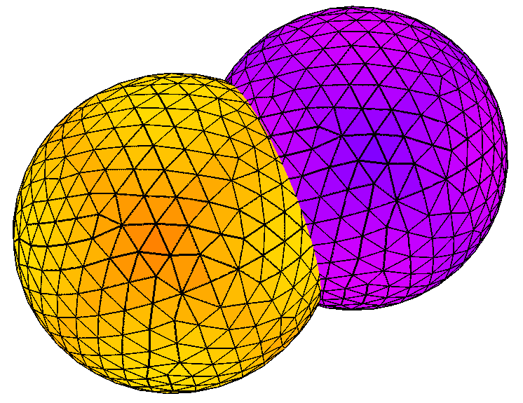
In the above figure, two spheres intersect. These spheres are two-manifold, and non self-intersecting. After intersection the results are as follows:
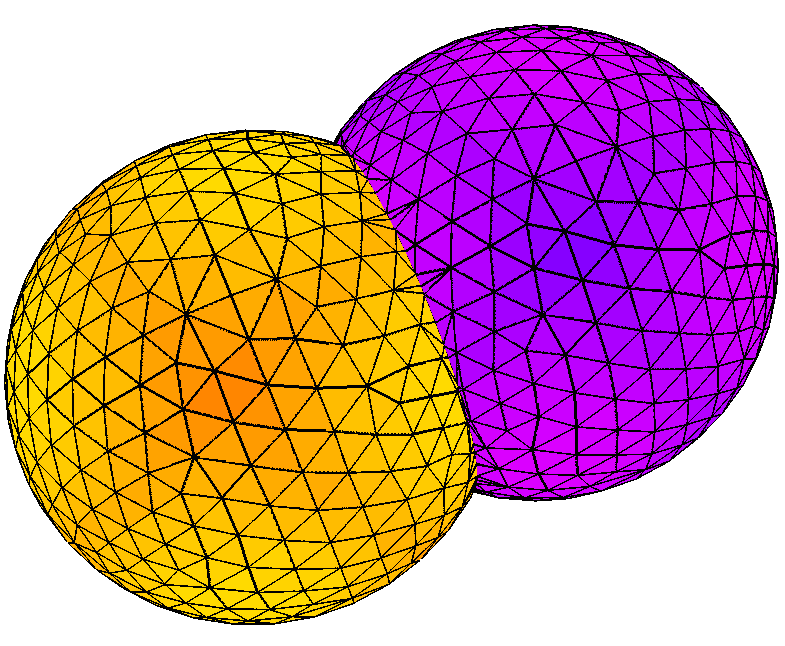
In the figure above, the spheres can be seen after intersection. Upon closer inspection, in the figures below, the individual spheres can ben seen. The circular intersection was captured on both spheres and forms a closed loop. These loops were used to separate the spheres into two surfaces so that the intersection can be repaired.
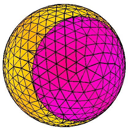
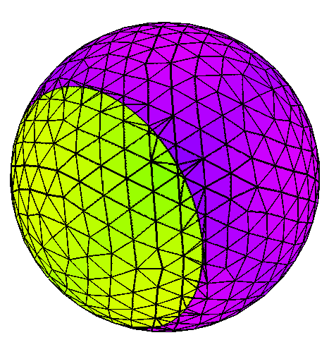
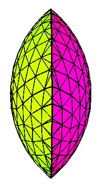
If the desired result was the wetted surface, the result would look like the original geometry. However, if the desired result were the interior of the spheres, then the result would look like the following figure. This shows that the intersection separated the spheres into two surfaces that can then be manipulated by the user to repair the intersection.
Miscellaneous Utilities

Reverse the face normal, i.e. reverse the face connectivity, of the selected Groups.
 |
 |
 |
 |