
Integrated Computational Materials Engineering (ICME)
Porcine Brain
Abstract

SHPB FE animation of the Von Mises Stress contours for a SHPB test. Upper movie insert is actual experiment and lower animation is FE simulation of test, at 550 s-1.
This research effort presents a coupled experimental/modeling study of the mechanical response of porcine brain under high strain rate loading conditions. Essentially, the stress wave propagation through the brain tissue is quantified. A Split-Hopkinson Pressure Bar (SPHB) apparatus, using a polycarbonate (viscoelastic) striker bar was employed for inducing compression waves for strain rates ranging from 50 – 750 s-1. The experimental responses along with high speed video showed that the brain tissue’s response was nonlinear and inelastic. Also, Finite Element Analysis (FEA) of the SHPB tests revealed that the tissue underwent a non-uniform stress state during testing when glue is used to secure the specimen with the test fixture. This result renders erroneous the assumption of uniaxial loading. In this study, the uniaxial volume averaged stress-strain behavior was extracted from the FEA to help calibrate inelastic constitutive equations.
Introduction
Traumatic brain injury (TBI), due to mechanical insult of the head, is a leading cause of death and life-long disability in the United States. The Center for Disease Control (CDC) has estimated that, on average, 1.4 million Americans sustain TBI every year, 20% of which are the result of motor vehicle-traffic accidents. In order to develop effective protective measures, better knowledge of injury mechanisms and the corresponding biomechanics of injury development in the brain are needed. SPHB is a novel experimental set-up to test and study the mechanical behavior of brain at injurious (high strain rates) loading conditions. To effectively model TBI conditions, the material properties of the brain in the range susceptible to traumatic injuries need to be understood. The authors discovered no studies to date that address the mechanical response of the brain in the range of 50 -750 s-1. Consequently, our research goal is first to present high strain rate data for porcine brain at strain rates in the range 50 -750 s-1, and second to study the stress state and inertial effects of the specimen during a SHPB test using FEA. An additional goal is to verify the assertion of Song et al. (2007) [1] on specimen geometry modification to counter inertial effects during high strain rate compression.
Materials and Methods
This section provides the methods involved in conducting experiments using a SHPB for soft biological materials and the FEA of the high strain rate experiment for obtaining the uniaxial loading direction stress (σ33).
- How to prepare biological specimens for testing in a SHPB apparatus?
- What is the protocol for conducting a test using a SHPB apparatus?
- An overview of the statistical analysis performed experimental data
- How to develop a Finite Element (FE) model for simulating the SHPB experiment on brain specimens?
Discussion
Experimental Results
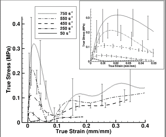
Figure 1: Experimental true stress-strain behavior with associated experimental standard deviation error bands for porcine brain specimen under high strain rate compression.The specimens used were cylindrical with a diameter of 30 mm and thickness 15 mm.
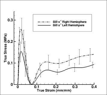
Figure 2: Experimental true stress-strain behavior with associated standard deviation error bands for porcine brain represented by the right and left hemispheres of the brain, at 550 s-1. The specimens used were cylindrical with a diameter of 30 mm and thickness 15 mm.
The mechanical response of the brain is highly strain rate dependent (Pervin and Chen, 2009)[2] as confirmed by Figure 1. The response is marked by initial yielding effect, followed by a softening trend, and then “hardening” at higher strains. These trends were consistent over the range of strain rates tested using the SHPB apparatus. Clearly, as the strain rate increased, the initial yielding increased. This increased yielding can be explained as the resistance of the cellular structures to rapid deformation. Since 65-80% of cellular structures in the brain are comprised of water, part of this initial yielding can be attributed to the water content (Neeb et al., 2010)[3]. Once the energy required to overcome the resistance offered by the cellular structures is met, cell walls rupture, leading to release of fluid within. This rupturing process is captured in the softening trend following the initial yielding effect. Upon further compression, fluids migrate into inter-cellular regions and cellular structures go through substantial volumetric deformation. The closer the cellular structures get to one another, the more the sample goes through inelastic deformation, involving aberrations and slippage between cellular macromolecular structures. As the specimen is further compressed at higher strains, more resistance is offered by the cellular structures. Here the specimen cannot deform further without breaking the long macromolecular chains of cellular structures. The macromolecular chain resistance gives rise to the strain “hardening” effect observed at higher strains. When analyzing the mechanical response differences between the left and right hemispheres of the brain, one might expect differences between the left and right sides of our brain consistent with the usually subtle but distinct differences between the left and right sides of our bodies (fingers, hands, feet, or facial features). Figure 2 shows the variation in the stress-strain behavior with the associated uncertainty. Similar results of weak anisotropy, due to anatomic location of specimen, was reported by Tamura et al. (2007)[4]. Figure 2 shows that there is a stress-strain variation between the left and right hemispheres; however, the uncertainty in the stress-strain behavior with cylindrical specimens used makes it 1difficult to distinguish the variation due to sample extraction location. Statistical analysis of the tangent modulus, peak stress and strain at the peak stress from the mean true stress-strain response confirmed that there is a statistical significance over the strain rates 50 – 750 s-1 (Table 1).
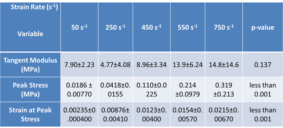
Table 1: Comparison of three parameters obtained from the true stress-strain response of porcine. The strain rates included are 50, 250, 450, 550 and 750 s-1.
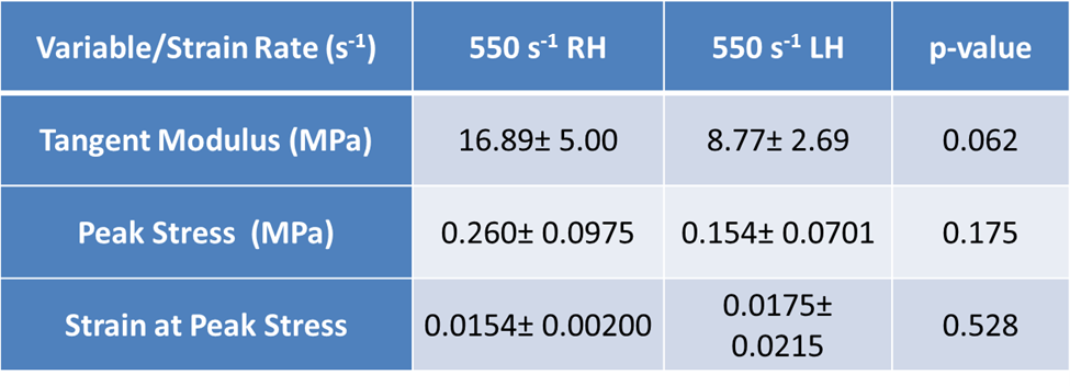
Table 2: Regional comparison of three parameters obtained from the true stress-strain response of porcine at 550 s-1. Regional variations were studied between samples extracted from right and left hemisphere of porcine brain.
For the peak stress and strain at the peak stress, with p<0.05, a significant difference has been recorded. Although we noticed an increasing trend in the tangent modulus, a statistically significant difference was not observed (p>0.05). On the other hand, while analyzing the difference in the three parameters due to sample extraction from the right or left hemisphere, no significant difference was obtained (Table 2). Figure 3 gives contour snapshots of σ33 at various stages of specimen deformation. Here the direction of σ33 is the loading direction. The contour plot at the peak of initial hardening effect vividly shows values of stress comparable to the experimental true stress value. Here compressive stresses are taken to be positive in the experiment. It is to be noted that σ33 is higher towards the central region of specimen than at the periphery. Figure 4 gives contour snapshots of σMisses at various stages of deformation. σMises contours in the specimen at the peak of the initial hardening effect show a different trend than that observed in σ33 contour, at the same stage. The region of maximum σMisses lies along a circular band towards the periphery of specimen, while the region of minimum σMises lies in the central region of specimen. The maximum σMisses values are comparable to the peak experimental true stress value. This implies that the maximum deviatoric stresses act mainly in the periphery of the sample. Figure 5, with 1st invariant of stress contour snapshots at different stages of deformation, shows results similar to Figure 3. 1st invariant of stress is highest in the central region of the specimen, which is similar to σ33 contours at the same stage. Figure 3 clearly shows that most of the axial stress σ33 is concentrated in the central part of the sample.
Finite Element (FE) Model Results
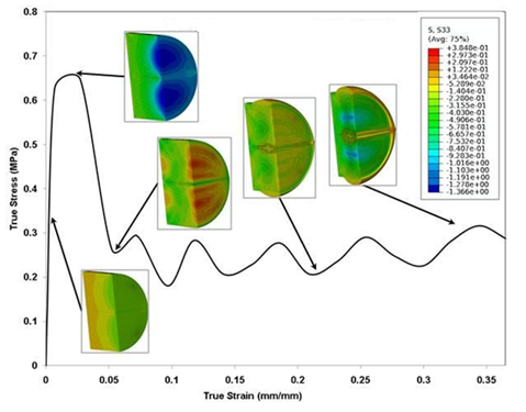
Figure 3: Contour plots of the loading direction stress (σ33) at different stages of the true stress-stress curve at a compressive strain rate of 750 s-1. The specimen sample is a solid cylindrical disk and compressive σ33 in the plot ordinate is treated as positive, while the contour level compressive σ33 are negative.
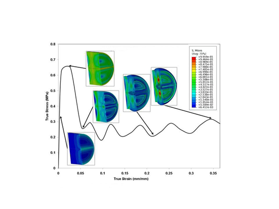
Figure 4: Contour plots of σMisses at different stages of the true stress-stress plot at a strain rate of 750 s-1. The specimen sample is a solid cylindrical disk and compressive σ33 in the plot ordinate is treated as positive.
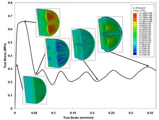
Figure 5: Contour plots of the pressure (first invariant of stress) at different stages of the true stress-stress plot at a strain rate of 750 s-1. The specimen sample is a solid cylindrical disk and compression in the plot ordinate and the contour legend are treated as positive.
Song et al. (2007)[1] asserted that the initial hardening trends, observed in Figure 6, are due to inertial effects, which they argued were not part of the material response. They inferred that the initial peak is a consequence of the radial inertia due to axial deformation acceleration stage. Song et al. (2007)[1], in their high strain tests, cut a circular hole in the specimen to mitigate inertial effects. If the specimen σ33 contour in Figure 3 was concentrated on the periphery, then removal of the central portion of specimen would be justified. However, as evident in Figure 3, the specimen σ33 contour plot values, especially at the peak of the initial hardening effect, are concentrated in the central region and are comparable to the stress values of the specimen obtained through the experiment and FEA (Figure 6). Hence cutting a circular hole in the specimen would remove a quintessential aspect of the material’s mechanical response.
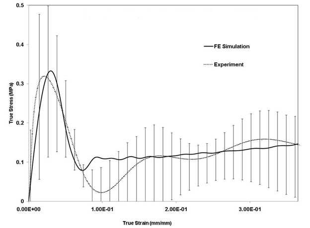
Figure 6: Comparison of experiment and Finite Element (FE) simulation σ33 for porcine brain sample compression, at 750 s-1. FE simulation σ33 were calculated by post processing the strain measurements from FE simulation through DAVID Viscoelastic software.
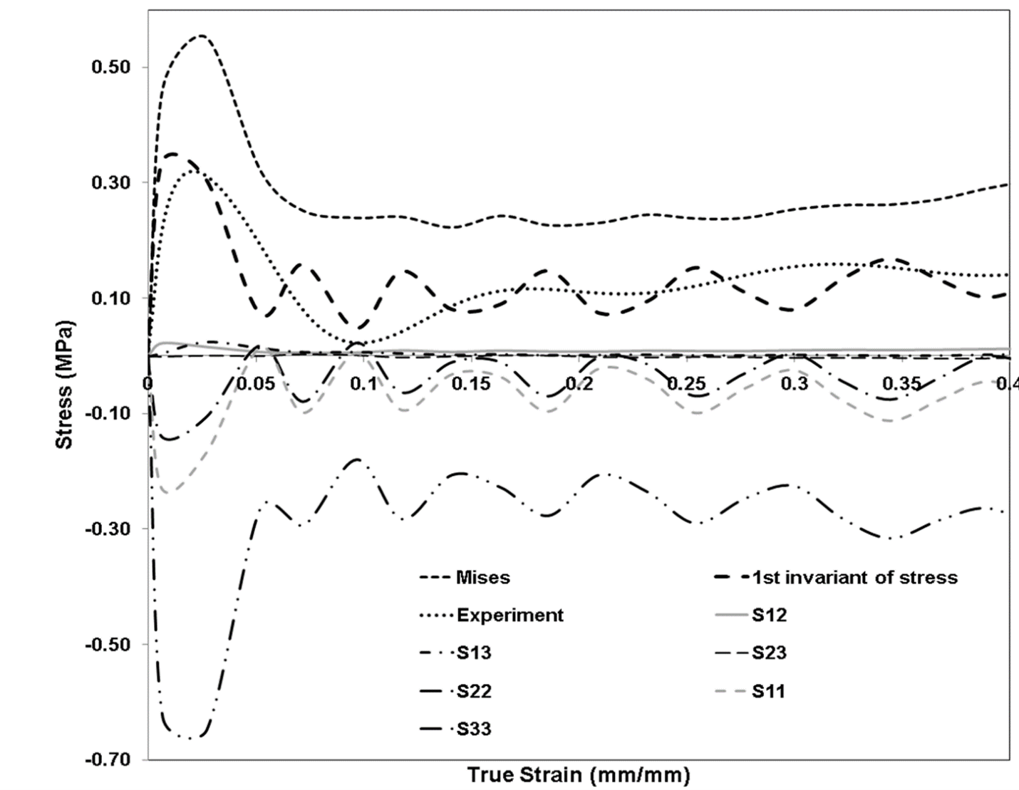
Figure 7: Comparison of Finite Element (FE) simulation pressure, σMises, σ11, σ22, σ33, σ12, σ23 and σ13 and experiment during deformation for cylindrical sample, at 750 s-1. Here compressive stresses are negative.
Figure 7 show plots of the various stress components versus loading direction sample strain during simulation of a SHPB test at 750 s-1. These plots were volume averaged over the specimen at each time step. The shape of the specimen considered for the simulation was cylindrical with no circular hole in the center. The plots indicate a strong presence of σ11 and σ22 stress components along with σ33. The values of σ11 and σ22 are comparable to σ33 for the entire simulation. Hence, a uniform stress state was not maintained during the testing procedure. Furthermore, the FE specimen 1st invariant of stress trend closely followed the experimental trend, indicating that the experiment could measure a 1st invariant of stress like term.
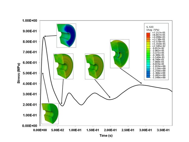
Figure 8: Contour plots of σ33 at ldifferent stages in a true stress-stress plot at a strain rate of 750 s-1. The specimen sample is a solid with a cylindrical hole in the middle (annular specimen). The specimens used in Finite Element (FE) simulation were annular with an outer and inner diameter of 30 mm and 4.5 mm respectively, and a thickness 15 mm.
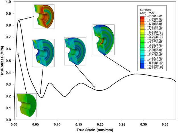
Figure 9: Contour plots of σMises at different stages in a true stress-stress plot at a strain rate of 750 s-1. The specimens used in Finite Element (FE) simulation were annular with an outer and inner diameter of 30 mm and 4.5 mm respectively, and a thickness 15 mm.
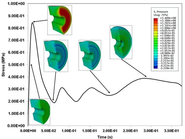
Figure 10: Contour plots of pressure at different stages in a true stress-stress plot at a strain rate of 750 s-1. The specimens used in Finite Element (FE) simulation were annular with an outer and inner diameter of 30 mm and 4.5 mm respectively, and thickness 15 mm.
In Figure 8, the FE simulation result (σ33) for the annular specimen produced a similar initial hardening trend, which indicates that cutting a hole in the sample may not reduce the initial hardening experienced by the specimen. The initial hardening trend is still prominent in σMisses and 1st invariant of stress contours for an annular specimen (Figures 9 and 10). Figure 11 shows history plots of the various stress components of an annular sample during simulation of a SHPB test at 750 s-1. The responses of stress components are similar to that of cylindrical sample with no circular hole (Figure 7).
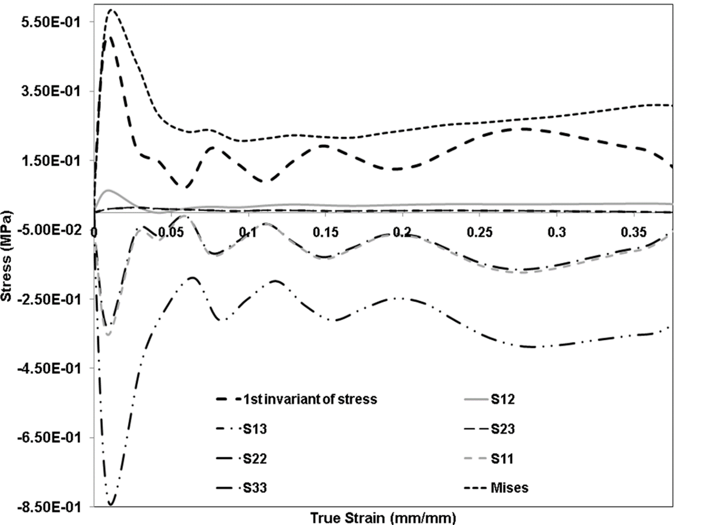
Figure 11: Comparison of Finite Element (FE) simulation σMises, σ11, σ22, σ33, σ12, σ23 and σ13, and experiment during deformation for annular sample, at 750 s-1. The experimental result corresponds to that of a cylindrical sample. Experimental data was added to give an idea of the range of stress components of annular specimen from FE simulation. Here again compressive stresses are negative.
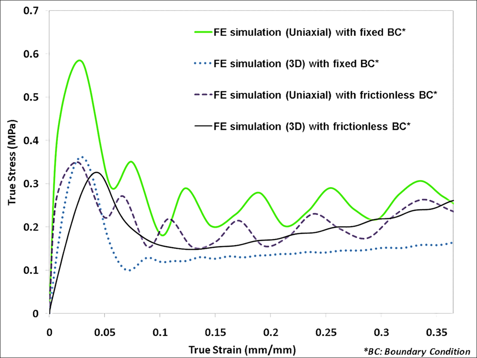
Figure 12: Comparison of uniaxial and 3-D true stress-strain plots for FE simulation with fixed BC and with frictionless BC on a cylindrical sample, at 750 s-1. The specimen had a diameter of 30 mm and thickness 15mm.
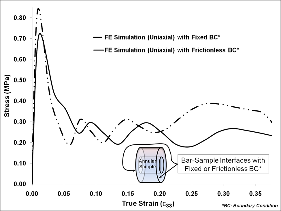
Figure 13: Comparison of uniaxial true stress-strain plots for FE simulation with fixed BC and with frictionless BC of annular sample, at 750 s-1. The sample had an outer diameter of 30 mm, an inner diameter of 9 mm and thickness 15 mm.
The initial peak in σ11, σ22 and σ33 are still observed in Figure 11 and are very similar to responses of σ11, σ22 and σ33 illustrated in Figure 7. In Figure 11, the peak values of σ11 and σ22 are comparable to σ33 for the entire simulation, which fall in the range -0.3 ¬ -0.8 MPa. Here σ11 (gray-dashed line) and σ22 (black-dash-dotted line) almost overlap one another. It is clear from Figures 7 and 11 that uniform stress state is not maintained in both cases. However, while the duration of the initial hardening trend is reduced for an annular specimen, to a certain extent, as the drop off of the hardening occurs at a lower strain, a similar duration reduction does not occur for a cylindrical sample (Figures 3,4,5,8,9 and 10). This reduction in initial hardening can be attributed to inertial effects, as discussed by Song et al. (2007)[1]. Reductions in σ33 hardening trends from the FE calculation (Figure 3 and 8) for the annular specimen confirm the presence of inertial effects. But, the reduced initial hardening trends in Figures 3 and 8 could be intrinsic to the material. Figures 3, 8, 9, and 10 show comparisons of FE simulation contours of σMisses and 1st invariant of stress, for cylindrical and annular specimen obtained from FE simulations at 750 s-1. The trends of σ33 and σMisses are similar in the initial stage (strain<0.15). Additionally, the usage of lubricated (frictionless) sample-bar interface, for a cylindrical sample, does lead to a closer representation of the uniaxial σ33 to the 3-D stress state (Figure 12). The reduction in the uniaxial peak stress due to change in the BC to a frictionless state was 42%. This reduction in peak stress reaffirms the implementation of lubricated sample-bar interface by Song et al. (2007)[1]. Furthermore, a similar trend was also observed in exercising fixed and frictionless BCs for the annular specimen (Figure 13). However, the reduction in the uniaxial peak stress was only 13%. In both cases (cylindrical and annular sample), the change in the sample-bar interface did not negate the initial hardening (Figures 12 and 13) as Song et al. (2007)[1] asserted. This implies that the experiment could be registering inertial effects as well as intrinsic material response, and actually measuring the 1st invariant of stress like term instead of the uniaxial σ33 stress response. Hence, the SHPB testing procedure should be investigated and further modified to test soft biological materials.
Acknowledgements
The authors would like to recognize the Center for Advanced Vehicular Systems (CAVS) and the Agricultural and Biological Engineering Department at Mississippi State University for supporting this work. This material is based upon work supported by the U.S. Army TACOM Life Cycle Command under Contract No. W56HZV-08-C-0236, through a subcontract with Mississippi State University, and was performed for the Simulation Based Reliability and Safety (SimBRS) research program. Also, this material is based upon work supported by the National Nuclear Security Administration, (Department of Energy) under award number [DE-FC26-06NT42755]. Finally, the authors would like to thank David Adams, Michael McCollum and Wilburn Whittington for their effort in this research.
Reference
1. Song, B., Chen, W., Ge, Y., Weerasooriya, Y., (2007), “Dynamic and
Quasi-static Compressive Response of Porcine Muscle,” J Biomech, 40 pp.
2999–3005.
2. Pervin, F., and Chen, W. W., (2009), “Dynamic mechanical response of bovine
gray matter and white matter brain tissues under compression”, J Biomech,Vol.
42, pp.731-735.
3. Neeb, H., Ermer, V., Stocker, T., and Shah, N. J., (2010), “Fast
quantitative mapping of absolute water content with full brain coverage”,
NeuroImage, 42 pp.1094-1109.
4. Tamura, A., Hayashi, S., Watanabe, I., Nagayama, K. and Matsumoto, T.
(2007), “Mechanical Characterization of Brain Tissue in High-Rate Compression”,
J BiomechSci&Eng, Vol. 2, No. 3, pp. 115-126.