


Tutorials: Topology Tutorial - UFO and Other Topology Functions
The best way to learn is to practice. Download the file ufo.igs.gz and read it into the SolidMesh program (see Basics and File I/O for help reading the file in) . Make sure you read it in with no glue and no trim.
More Trimming
1. The image should look like this. You may have to make sure that the surfaces are turned on in the Visible Graphics List.
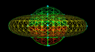
2. If you bring the ufo in and try gluing it without trimming the top
and bottom surfaces, you will have some errors. Try doing this and then
select  to see the topologically invalid entities.
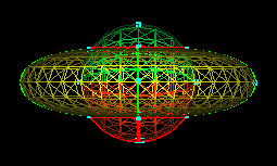
3. Restarting with the original unglued file, select the top and bottom surfaces (groups top and bottom).
4. Now select  .
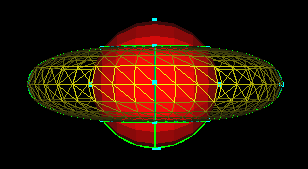
You will see that the bottom surface (group bottom) trimmed nicely, but
the top surface will not trim. You will also get an error message saying
that the surface could not be trimmed. You can select
.
You will see that the bottom surface (group bottom) trimmed nicely, but
the top surface will not trim. You will also get an error message saying
that the surface could not be trimmed. You can select  to unpick the picked surface and curves. Note that the picked curves
when trimming mark the problem areas for that action, but this can be misleading
because the selected curve may or may not be the problem. The selected
curve is merely the curve where the algorithm died trying to find the trimming
loop.
to unpick the picked surface and curves. Note that the picked curves
when trimming mark the problem areas for that action, but this can be misleading
because the selected curve may or may not be the problem. The selected
curve is merely the curve where the algorithm died trying to find the trimming
loop.
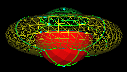
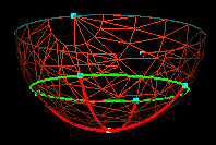
5. Since the top surface would not trim, select it, turn
it off, and toggle to get a better look at this surface. Notice that
the surface has many extra lines (shown selected in red) which could cause
problems when trimming. The program was not sure which part to trim
because there was no defined area for trimming. The desired trimming
loop is shown by the unselected green curves. For more explanation
on this, see Trim on the Topology page. The
curves that are causing problems are only construction curves and no longer
needed. Select the unwanted curves and
 .
.
6. Hit  to turn the other surfaces back on. Now pick the top surface (the
untrimmed one). Then select
once again.
to turn the other surfaces back on. Now pick the top surface (the
untrimmed one). Then select
once again.
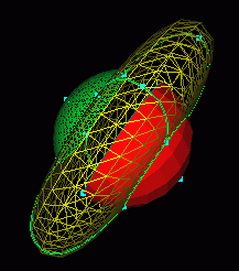
7. The surface should trim easily, and you will get the result shown to the right. Deleting the construction curves removed any ambiguity about which loop was the trimming loop and the surface trimmed.
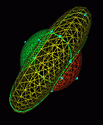
8. Now select  .
When there is a message in the message area stating that the gluing is
complete (Done), select
to check the topology. If the model is not topologically valid, check
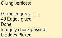
will pick the topologically invalid entities. In this case though, you
should get a message in the message window stating that the check passed.
You can now create your surface grid.
.
When there is a message in the message area stating that the gluing is
complete (Done), select
to check the topology. If the model is not topologically valid, check
will pick the topologically invalid entities. In this case though, you
should get a message in the message window stating that the check passed.
You can now create your surface grid.
Glue and Unglue
1. The tolerance of the ufo when it is read in is originally set to 1.
To change this, you can either read it in using the  ,
or you can change the tolerance once it is read in. If you set the
tolerance to
,
or you can change the tolerance once it is read in. If you set the
tolerance to  ,
and select ,
you may notice that not as many edges were glued. Select
to see the unglued edges.
,
and select ,
you may notice that not as many edges were glued. Select
to see the unglued edges.
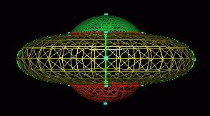
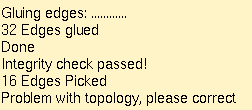
2. You will also get an error message saying how many edges there were that were not topologically valid, in other words, not glued. They will be the edges you see picked.
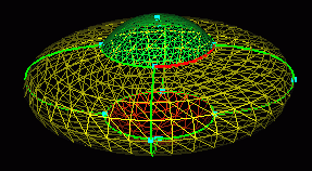
3.
the pick list and pick two curves to
at a time. They should be one on top of the other as seen. You should only
see one curve.
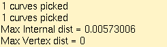
4. When pressing
with only two curves picked, the message window should display a note giving
the distance that the curves had between them (or the distance they were
apart). A number slightly larger than the distance given would probably
make a good tolerance level. If the tolerance level is changed to a high
enough value to just barely include all of the curves which were not topologically
valid when gluing the entire model, you can try gluing the model again
with the new tolerance. You may still find a couple of curves that are
further apart that you would either need to glue separately, or change
the topology to include the distance they are apart. This is something
that could take a lot of practice.
5. When changing the topology, it is very important to make sure the level
is not too high. You can reload the ufo to try this exercise and see what
happens. If you bring in the ufo untrimmed and unglued, go ahead and trim
the top and bottom surfaces with the normal tolerance level set. You can
then change the tolerance level to a rather large number like 15. Then
press
and see how long it takes to get done gluing. The newly glued model will
have only one point and/or one curve because it tried to glue together
everything within a distance of 15. This can cause a lot of trouble when
dealing with grid generation and other things.
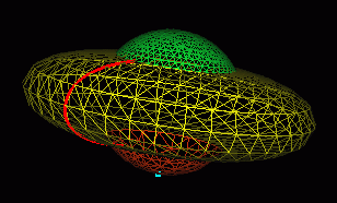
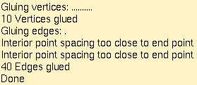
6. When gluing with a tolerance that is too large, you may also get an error stating that the interior point spacing is too close to the end point. This means that the areas are concentrated into one place because the space in between them is too small to include. The program now treats all of the curves and/or points of the model as the one curve and/or point that is visible after gluing.
7. In the surface grid generation area, you can have even more problems
with the spacing by trying to apply spacing to the point that is there.
If you select  ,
you will get the following picture.
,
you will get the following picture.
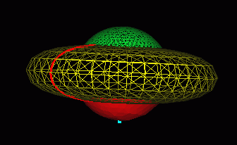
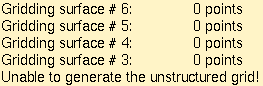
8. You will probably get an error message showing that it tried to generate the surface grids, but then there was some kind of problem.
9. Select the only remaining curve and  .
You will get the image to the right. You can see that some curves
and points are missing. The curves that did return were all glued
to the single curve you just unglued.
.
You will get the image to the right. You can see that some curves
and points are missing. The curves that did return were all glued
to the single curve you just unglued.
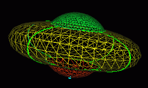
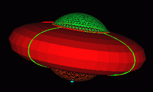
10. Now select and you will have several objects picked. This means that they are concentrated
into one place and actually should be much more spread out. You can read
more about the exact definitions for degenerate objects under the Degenerate
section of the Topology page.
and you will have several objects picked. This means that they are concentrated
into one place and actually should be much more spread out. You can read
more about the exact definitions for degenerate objects under the Degenerate
section of the Topology page.
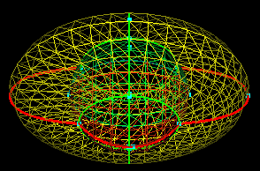
11. Again, read the ufo file back in , select
and then pick the curves as shown. Select  while they are picked.
12. Now select  so that you can see the curves by themselves.
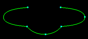
13. If you select two curves that are already attached by an endpoint as
shown, you can try to
them.
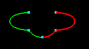
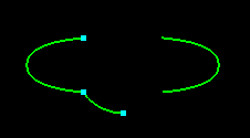
14. You will get an error and some very strange curves after gluing. You should only glue curves of approximately the same location in space and of approximately the same length. If either one of these specifications is broken while gluing curves, you may not see the entire curve or all of its endpoints anymore, as seen here. They are still present, but they are glued to the endpoints of the other curve.
Display Resolution
15. The purpose of changing the resolution of a surface is to view the
surface in more detail. As the resolution of a surface is made larger,
more points go into the construction of that surface. You can pick
a surface and  to find what the current resolution of the surface is. It will appear in
the message area.
to find what the current resolution of the surface is. It will appear in
the message area.
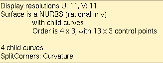
16. By default when read in, surface display resolution is set to 11x11.
In  ,
you can change the resolution to any desired resolution. You must then
pick a surface on which you want to change the resolution.
,
you can change the resolution to any desired resolution. You must then
pick a surface on which you want to change the resolution.
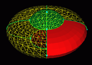
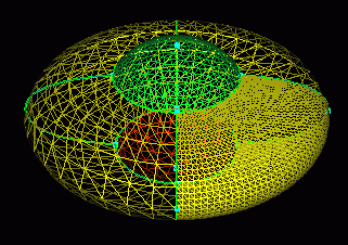
17. If you leave the default at 41 and select ,
you will get something that looks like this. As you can see, the surface
is much more defined than it was before.
18. The  toggle is supposed to calculate the best resolution for the picked surface.
For large surfaces, this may cause the surface to display with too many
points making rotation, translation, etc. difficult. You can try this anyway
by selecting the same surface as before, toggling
toggle is supposed to calculate the best resolution for the picked surface.
For large surfaces, this may cause the surface to display with too many
points making rotation, translation, etc. difficult. You can try this anyway
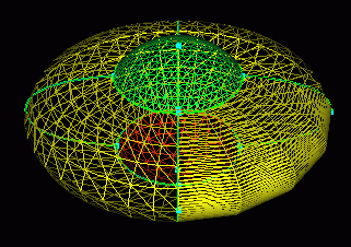
by selecting the same surface as before, toggling  and depressing .
You should get a surface that looks like this one.
and depressing .
You should get a surface that looks like this one.
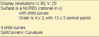
19. If you select that surface and hit ,
you may find that the resolution is no longer the same in both U and V
as before. You can practice changing the resolution of surfaces as much
as necessary, but you can also change the resolution of curves to make
them more defined and smooth. You can read more about how to change the
resolution under Resolution in the Topology
page.
 |
 |
 |
 |