


Tutorials: Structured Surface Grid - Assigning Point Spacing and Volume Grid Generation
For some applications, a structured surface grid is desired. AFLR has the ability to generate a boundary layer with hexahedral elements; but only from an quad-based surface grid. Download the file ufo_repaired.igs.gz to get started on the structured surface generation and subsequent hexahedral boudary layer generation.
1. Read the file ufo_repaired.igs.gz in with gluing and trimming enabled.
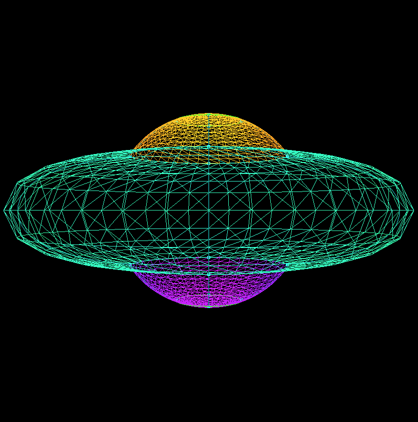
2.
Select all surfaces except for the circular surfaces on the Top and Bottom. This is most easily accomplished by selecting all the surfaces and then un-picking those surfaces. Toggle  and
and  and click
  .
.
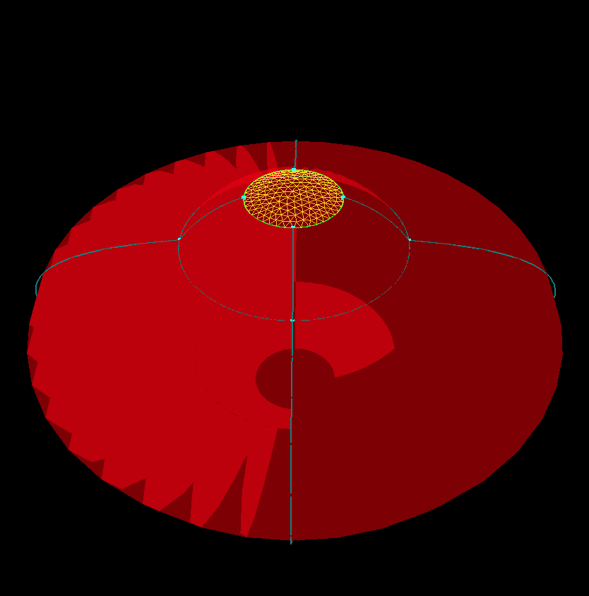
3. .
Generate the structured surface grid by pressing  and then
  .
.
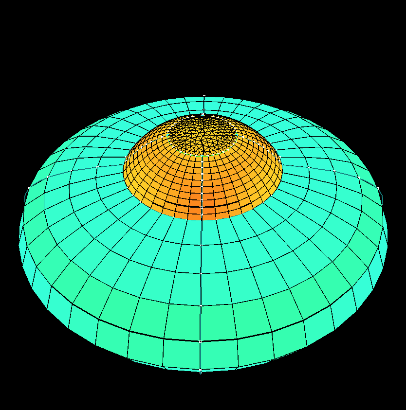
4.
Select the curve shown in red and enter 40 in the  and press
  . Then generate the surface grid again by pressing and then .
5.
Notice that the curve opposite of the curve altered has the same resolution and that this has been propagated to the adjacent surfaces all the way down the Bottom. This is required for the structured surface algorithm to generate the surface grid. Therefore it is done automatically. Next, select all of the curves, reset the value in to 11, press , and regenerate the surface grid to produce a grid like that seen in Step 3.
6.
The surface grids that have been generated thus far have been with generated by altering the number of points on a curve and having the point distribution on the curves set to  . In order to have a different point distribution, the point spacings on the individual points need to be changed. However, this cannot be done while the distribution is set to . To changed the point distribution, first select a curve and change and press
  . Note that if the number of points on the edge changes, the number of points on opposite opposite curves will subsequently changes.
7.
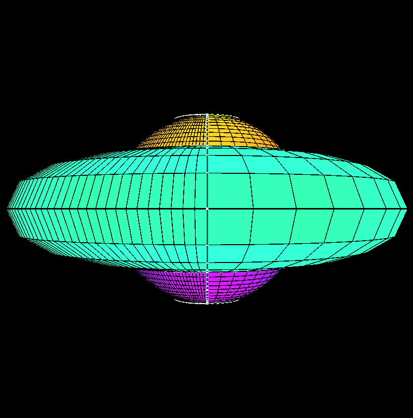
First, we will increase the grid resolution of the four curves on the ouside of the Saucer. This will allow us to group points close to the Top without sacrificing grid quality on the rest of the surface. Select the four curves shown in red in the figure and increase the value in to 50 and press . Regenerate the surface grid.
8.
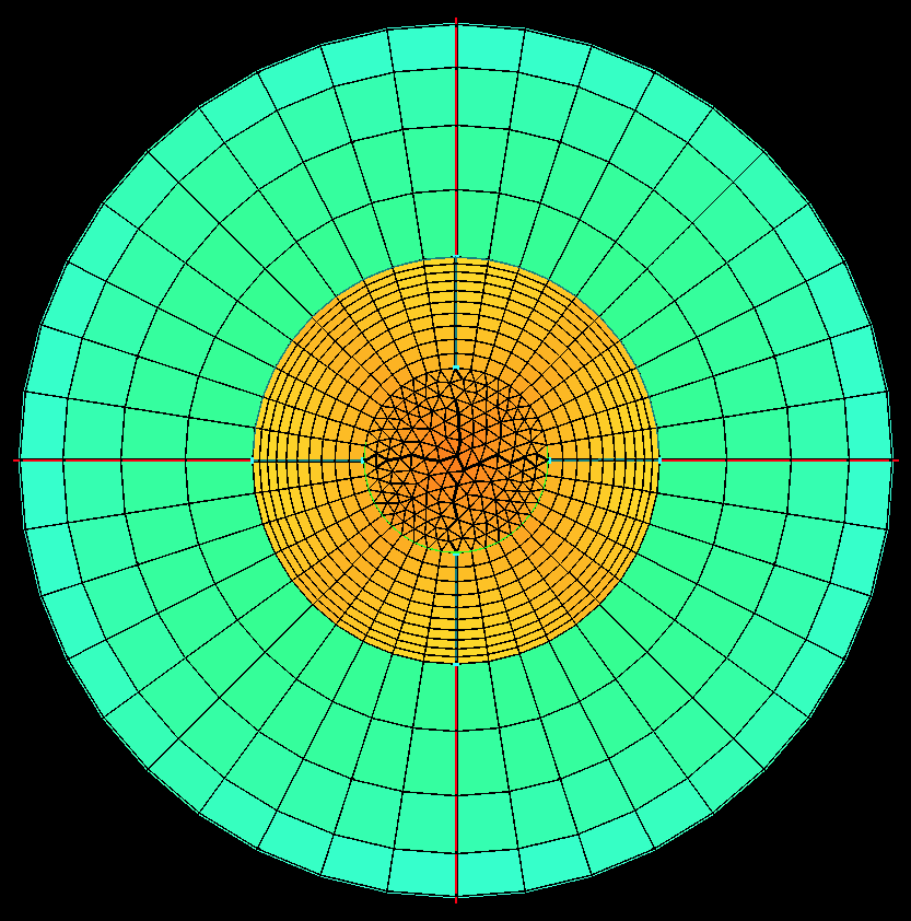
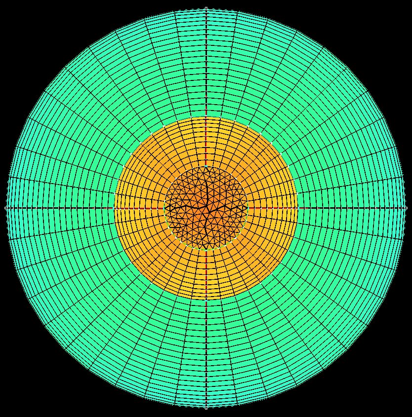
Next, select the eight curves shown in red in the figure and change to  and press .
9.
Select the four points shown in red (outer points on top surface of Top) and change the value in  to 0.267542 and press
  to apply the point spacing.
10.
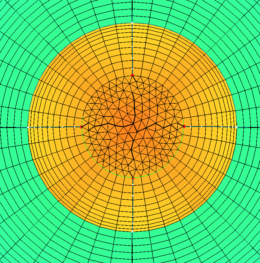
Select the four points shown in red (outer points of lower surface on Top) and change the value in to 0.0387329 and press to apply the point spacing. Regenerate the surface grid.
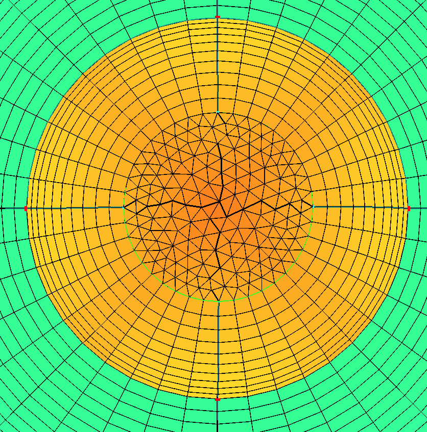
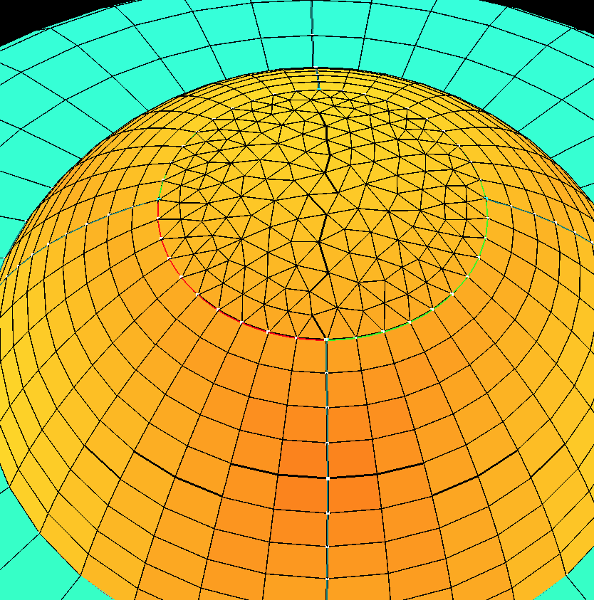
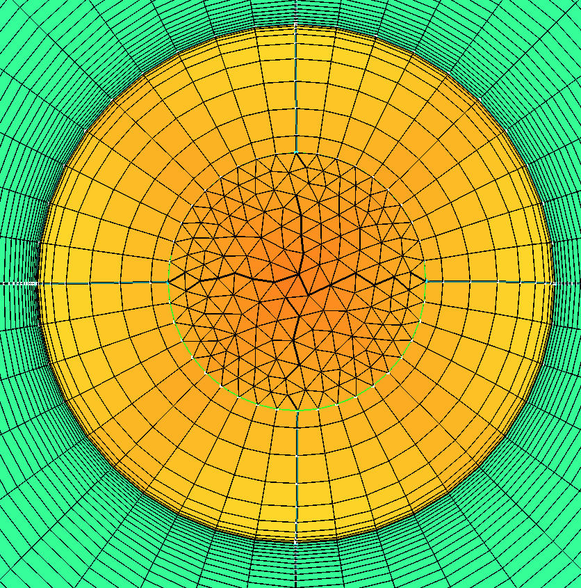
11. The figure to the right shows the increase resolution around the junction of Top of Saucer.
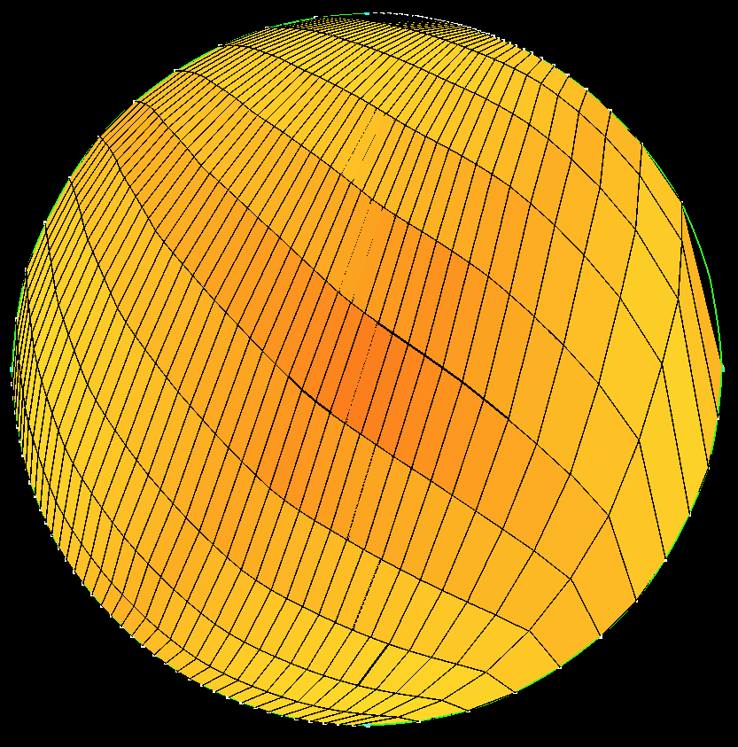
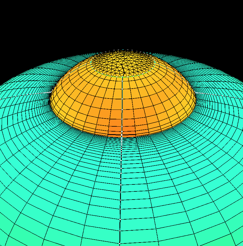
12. The figure to the right shows the increase resolution around the junction of Top of Saucer from another angle.
13.
Next, select all of the groups and toggle  on and press . Then change
  to "Tet/Prism/Pyramid/Hex". Next, press
  to generate the volume grid. Once that is done, press
  to read in the volume grid. Turn off group "Saucer", press
  to create a cutting plane, and you can see part of the grid that was generated inside of the UFO.
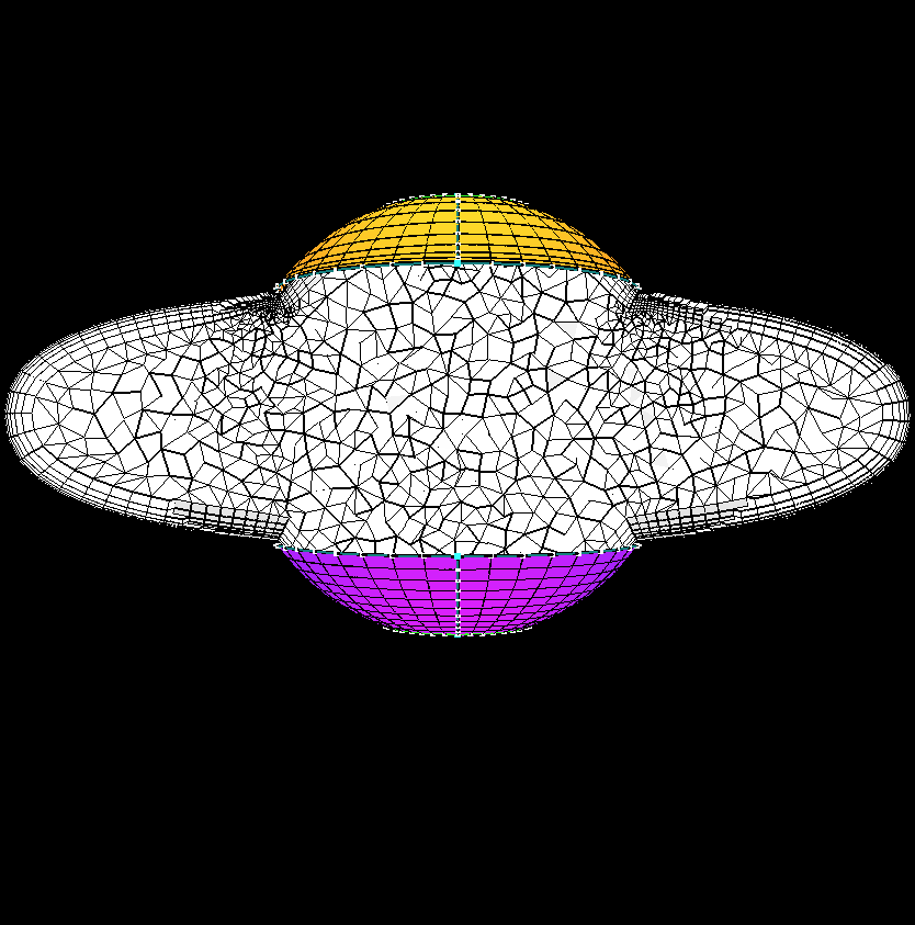
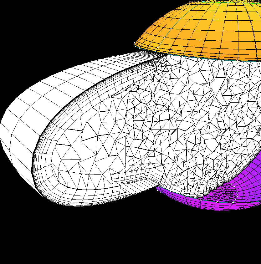
14. The picture in this step shows the hex boundary layer elements as well as the prism/pyramid/tet transistion to the isotropic region of the grid. Note: Quads can be used to generate the Tet only and Tet/Prism/Pyramid boundary layer grids, but the surface quads will be split into two trias. Note also how the grouping of the points at the junction of the Top and Saucer affected the volume grid.
 |
 |
 |
 |