


Planar Surface Grid Generation

Planar Surface Grid Generation Applications
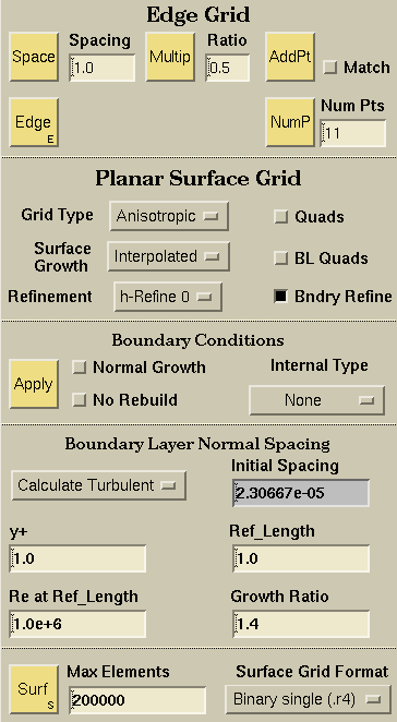
SolidMesh provides a user friendly front-end to the Advancing-Front/Local-Reconnection 2D (AFLR2) unstructured grid generator. AFLR2 is a stand-alone unstructured triangular element grid generation system. AFLR2 generates a triangular isotropic surface grid or a mixed element (triangles and quadrilaterals) anisotropic boundary layer surface grid from an edge grid discritization.
Edge Grid:

A point spacing is a physical dimension applied to curves and curve end points to control edge grid distributions. Given a set of point spacings on a curve, a 1D Advancing Front algorithm is used to compute the number of grid points and the linear distribution along that curve. To apply point spacings, pick any number of points, set the desired spacing, and hit return within the Spacing field; or set the desired spacing and hit the Space button. Applying a point spacing will automatically update all edge grids attached to the points. Any surface grids that depend on the edge grids will automatically be flagged to be recomputed. There are 3 methods used to apply point spacings:
- Pick any number of end points. CAUTION:Make sure the pick limit is set to "Point" to ensure that the end point is picked, and not the interior of an adjacent curve.
- Pick a point in the interior of a curve. This will create a new point at the location you pick. To remove the point spacing, simply delete the point. CAUTION: Do not specify an interior point spacing that is too close (within gluing tolerance) to the end point.
- Pick a point and a curve. This will create a new point at the closest distance from the point to the curve. This is useful when trying to match point spacings on curves that are close to each other but have varying locations of end points.

 Multiply Point spacing
Multiply the point spacing by the ratio specified in
the ratio field. This is a quick way to add or remove points and
maintain point spacing distributions.
Multiply Point spacing
Multiply the point spacing by the ratio specified in
the ratio field. This is a quick way to add or remove points and
maintain point spacing distributions.

Add a single grid point to a given curve with the same value end point spacings. This is useful for very small curves that need an additional interior point, but you do not want to compute the required end point spacings. NOTE: This function does not work unless both end point spacings have the same value.
Adds the indicated number of points to the selected curves. The Num Points button calculates the required spacing at the curve end points, based on arclength, to insert this desired number of points. The required spacing is then applied to the end points, and the points are inserted.

The Matched spacings on/off toggle determines whether a point spacing will be altered to reflect the shortest curve arc length adjacent to the given point. If match spacings is on, any picked point spacing that is larger than the shortest adjacent curve arc length will be set to match the shortest adjacent curve arc length. This is extremely useful when generating initial grids for very complex geometries. Examples demonstrating the use of Matched spacings are shown here.

To draw edge grids for all visible surfaces, you only have one thing to do: select the Edge button. If any edge grids have not been initialized (or had their point spacings set) then a resolution of 11 points will be used.
Planar Surface Grid Options:

The grid type selector allows you to specify either an isotropic or anisotropic surface grid:
- An isotropic grid is used for Euler calculations. The surface grid point placement distances are interpolated from the edge grid.
- An anisotropic grid is used for Navier-Stokes viscous calculations where the boundary layer must be resolved. An anisotropic grid needs a boundary layer spacing and growth rate in addition to the edge grid. A normal point placement technique is used to create right-angled triangle or quadrilateral elements.

The element size in the field is by determined using interpolation to smoothly propagate the point spacing within the field from the boundary surfaces. With optional growth, the element size is determined from interpolation and geometric growth normal to the boundary edges. There are four options available:
- Interpolated no growth specified, growth entirely determined by interpolation.
- Moderate growth normal to the edge at a geometric growth rate of 1.2.
- Highgrowth normal to the edge at a geometric growth rate of 1.5.
- Very high growth normal to the edge at a geometric growth rate of 2.0.

h-refine (element subdivision) the grid the specified number of times.

Combine triangular elements to form as many quadrilateral elements as possible within the quad element quality constrains. Advancing-point point placement for right-angle isotropic elements is automatically used with the quadrilateral element option. If the h-refinement option is used, then the h-refined grid will contain only quadrilateral elements.
Combine triangular elements in the boundary-layer only to form as many quadrilateral elements as possible within the quadrilateral element quality constrains. If the h-refinement option is used, then the h-refined grid will contain refined quadrilaterals and triangles.
Refine the boundary up to "value" times if adjacent boundaries are too close to each other.

Planar surface grid options may only be applied to groups. To apply a set of boundary conditions to a group, select the group, set all of the appropriate boundary condition toggles and select the Apply button.

The Normal Growth toggle specifies if a group of edges is a viscous boundary layer. If it is, and a boundary layer type grid is specified, the planar grid generator will build an anisotropic boundary layer grid off of these edges. NOTE: If you have specified an anisotropic type grid, there should be at least one group specified as a viscous boundary layer.

The No Rebuild toggle specifies that the edge grids in the applied group that are attached to viscous edges are not to be rebuilt. The affected edge grids will reflect the specified point spacings and not the normal spacing.
The transparency type chooser specifies if a group's edge grid forms a transparent control surface in the interior of the surface grid. Line and point sources can be created by placing a curve or vertex in a group with this boundary condition applied. The curve edge grid and the vertex will be used as sources in the surface grid depending upon the transparency type selected using the pull-down menu. There are three options available:
- Adapt Adaption sources are point sources used to refine the final surface grid.
- Fixed Point Fixed-point sources are points sources added to the initial triangulation.
- Fixed Curve Fixed-curve creates an interior surface using the specified curves edge grids. The points of the edge grid are added to the initial triangulation and the boundary edges remain in the final surface grid. Normal growth can be applied to fixed-curves.
- Fixed Curve-del Fixed-curve creates an interior surface using the specified curves edge grids. The points of the edge grid are added to the initial triangulation but the boundary edges are removed from the final surface grid.
Anisotropic Variables:
Calculate the boundary-layer growth assuming a laminar boundary-layer velocity profile.
Boundary-Layer Fraction
Specify the fraction of laminar boundary-layer thickness to use in determining the initial spacing normal to boundary-layer surfaces. When the BL fraction value is changed, the Boundary-Layer Fraction text field becomes active and the Initial Normal Spacing field becomes inactive (grayed background). The corresponding Initial Normal Spacing is computed using the specified Reynolds Number and Reference Length
Calculate the boundary-layer growth assuming a turbulent boundary-layer velocity profile.
Specify the y+ for a turbulent boundary-layer to use in determining the initial spacing normal to boundary-layer surfaces. When the y+ value is changed, the y+ text field becomes active and the Initial Normal Spacing field becomes inactive (grayed background). The corresponding Initial Normal Spacing is computed using the specified Reynolds Number and Refernce Length.
Specify the initial normal spacing normal to the boundary-layer surfaces. When the value of the initial normal spacing is changed, the Initial Normal Spacing text field becomes active and y+ (or BL Fraction) field becomes inactive. The corresponding y+ is computed using the specified Reynolds Number and Refernce Length.
Specify the reference Reynolds number to use in determining the parameters that control spacing normal to boundary-layer surfaces. The value of the Reynolds number specified is the Reynolds number at the Reference Length. When the value of the Reynolds number is changed, either the value of y+ or Initial Spacing is updated, depending on which is active.
Specifies the reference length in grid units where the Reynolds number is specified. When the value of the reference length is changed, either the value of y+ or Initial Spacing is updated, depending on which is active.
Specify the boundary-layer normal stretching ratio.
Grahical Explaination of Boundary-Layer Growth
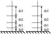
ds1 = r1*ds0
ds2 = r2*ds1
ds3 = r3*ds2
r2 = Growth Mult * r1
r3 = Growth Mult * r2
Surface Grid Generation:
Specify the maximum number of elements allowed in the surface grid.
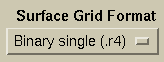
Specify the output format for the surface grid.

Launches the aflr2 surface grid generator using the specified options described above. Launching the surface grid generator will write out an edge grid, any transparent grid files, and a script with all of the specified options.
 |
 |
 |
 |