
Powder Metallurgy
Developing the ability to predict density distribution, monotonic plasticity, damage and the cyclic damage progression is imperative for the design of Powder Metallurgy (PM) components that will experience overloads during in-service life due to impacts, rough ground, and crash environments. CAVS researchers have developed mathematical-based models for PM manufacturing process, validating the compaction and sintering processes.
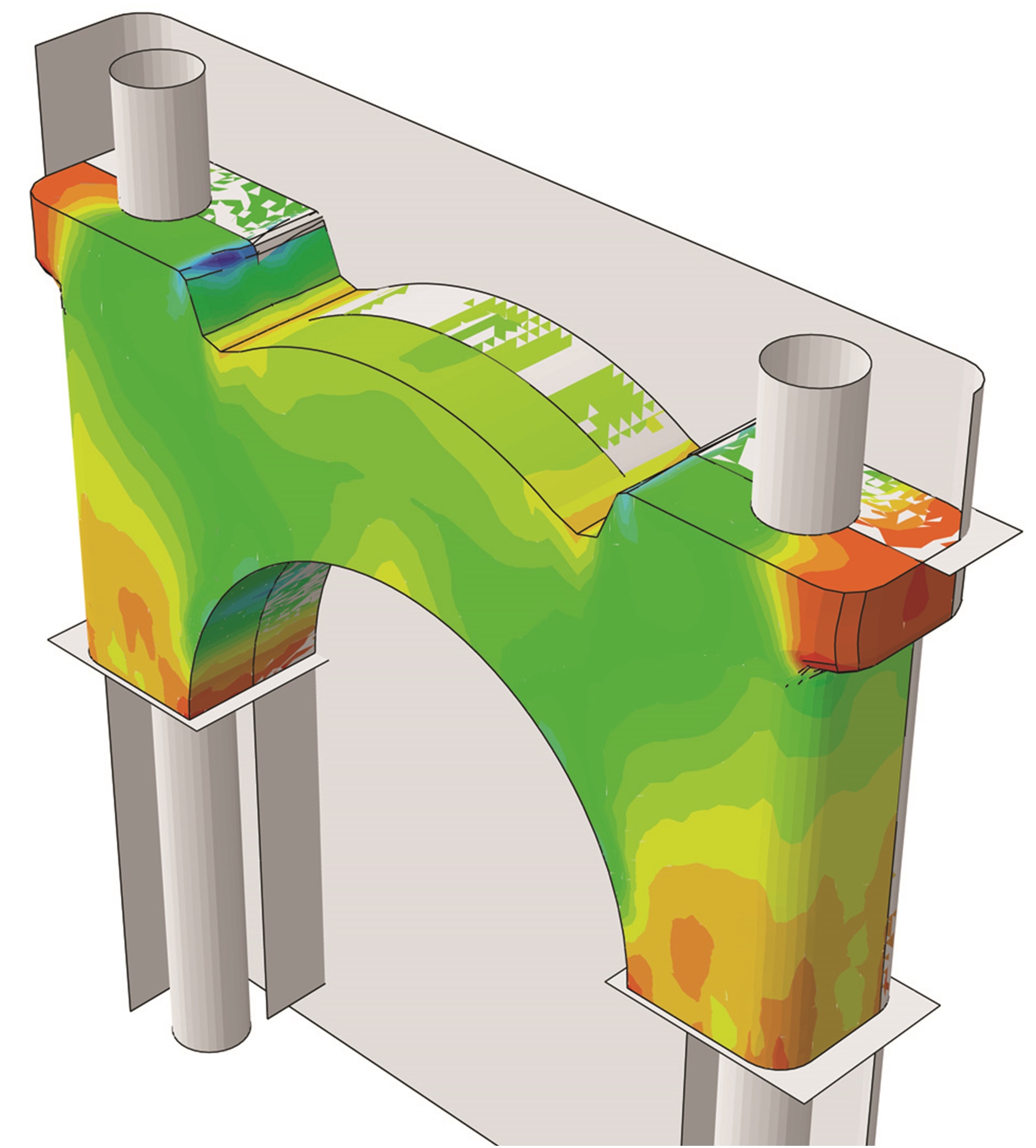
FEA simulation showing the MBC green density distribution at the end of compaction (in the die) for a FC-0208 0.6% Acrawax material.
Initially, the material history is captured and carried throughout the compaction and sintering processes, in order to predict the density distribution. Once the density distribution is know, mechanical properties are mapped in the PM sintered portion using mechanical tests of tension, compression and torsion and performed on samples at different densities, temperatures and strain rates. A finite element analysis of an experimental fatigue fixture is performed, which reproduces similar loading conditions than those of in-service life conditions. Using a Multi-Stage Fatigue (MSF) model implemented in Abaqus, the fatigue life is then evaluated on a PM automotive component, the main bearing cap (MBC), and results are compared to experimental fatigue tests.
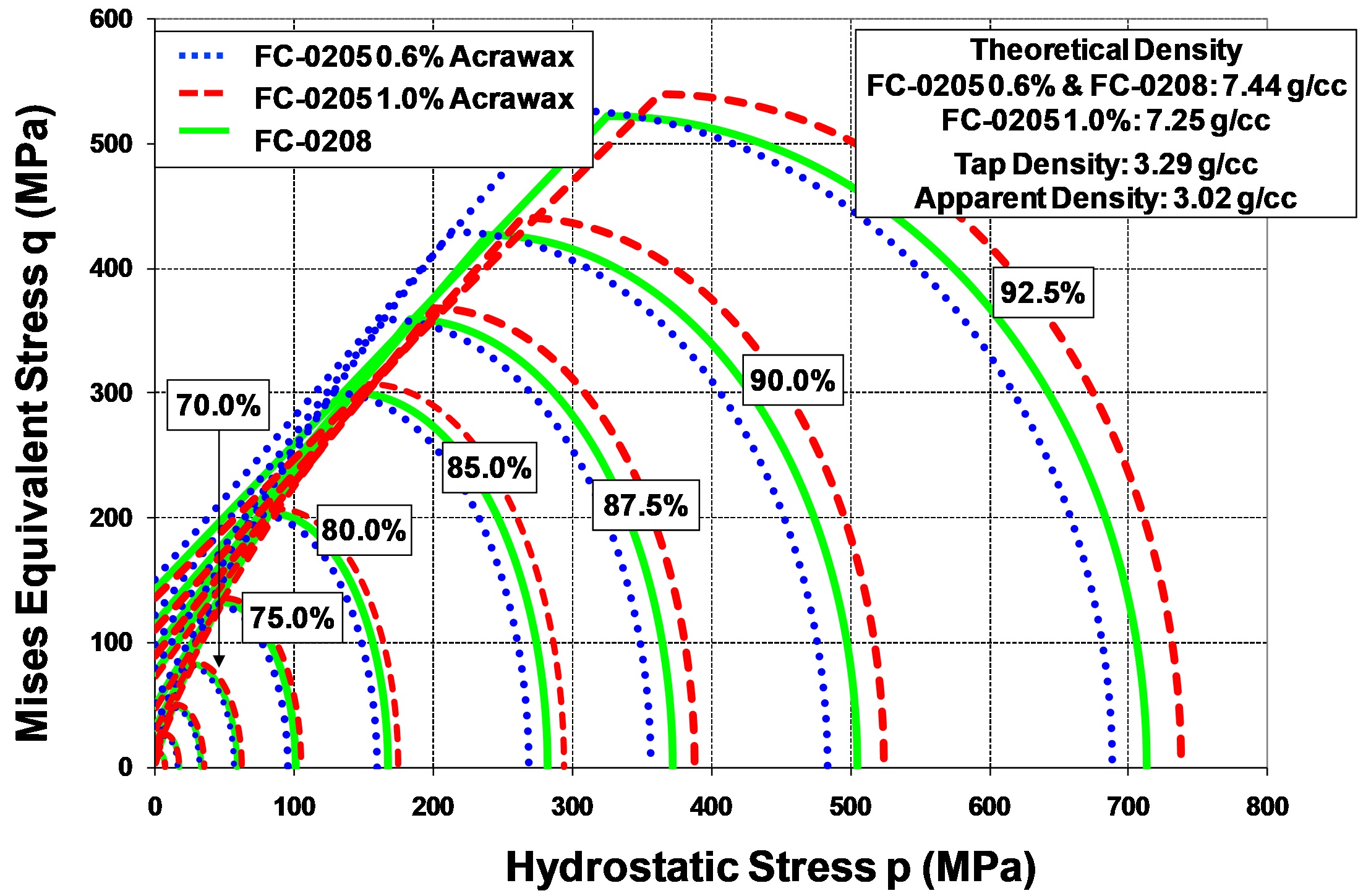
Isodensity curves in the p-q plan for FC-0205 and FC-0208 powders.
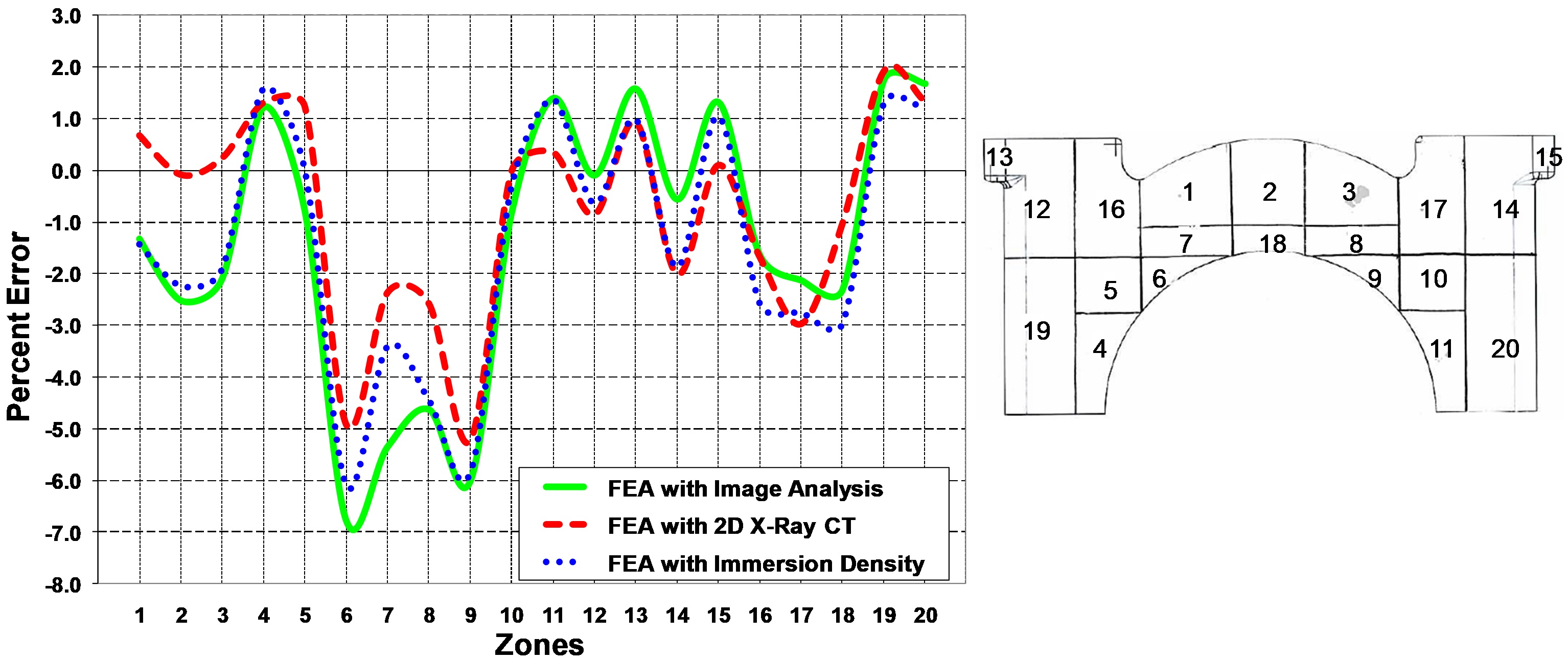
Density comparison in terms of percent error between numerical values and density measurements for 20 different zones.
Compaction Modeling
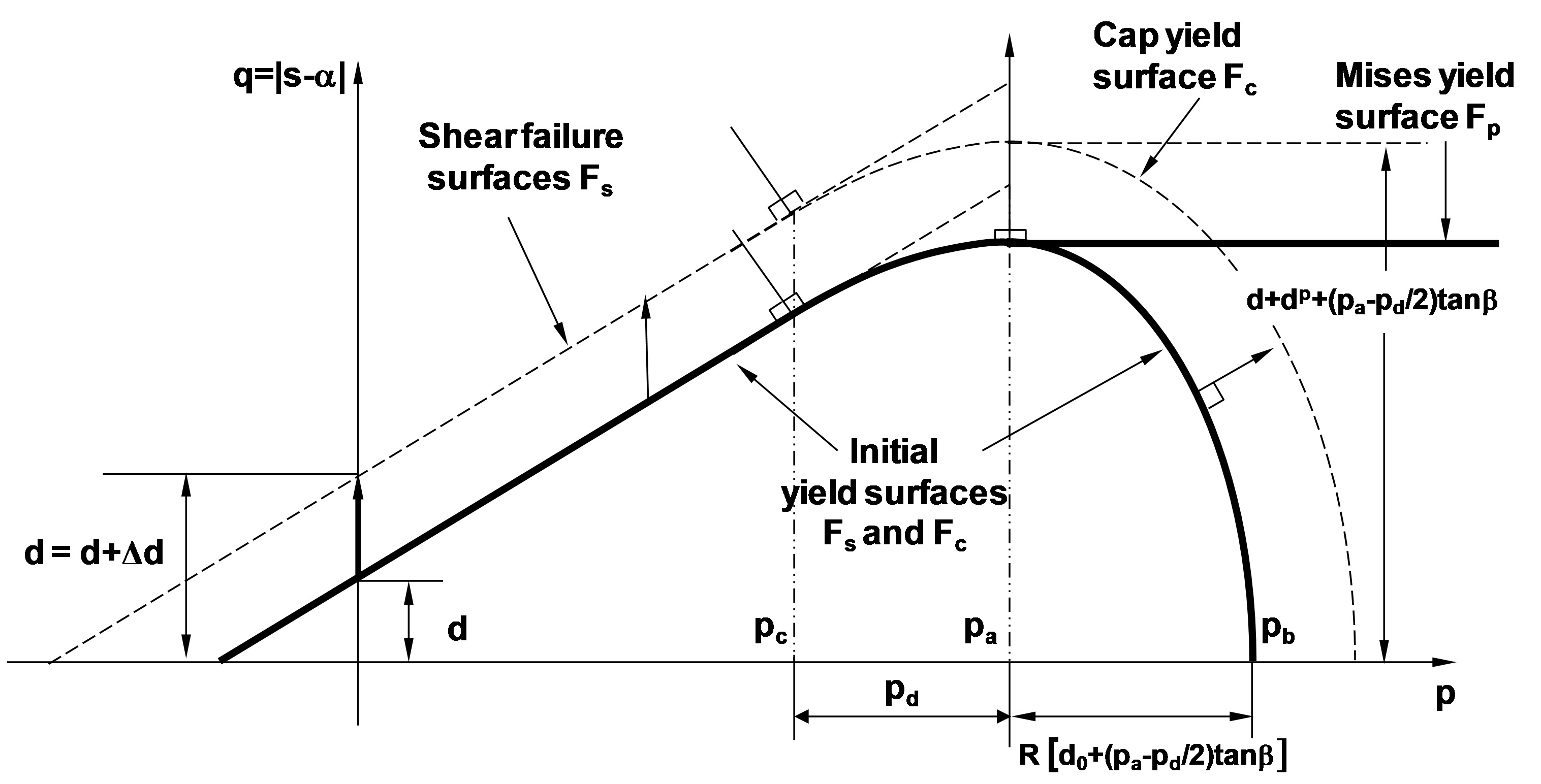
Modified Drucker-Prager/Cap Model: yield surfaces in the (q–p) plane.
Die compaction is the first consolidation process of the PM press-sinter process. To model the powder behavior during densification, a modified Drucker-Prager/Cap material model is used. The model was originally proposed by DiMaggio and Sandler for soil mechanics.
The plastic flow is defined by two dissipation potentials that are respectively non-associated to the failure envelope Fe in the low pressure region, and associated to the cap yield surface Fc in the high pressure region:

where β is the material's angle of friction and d is its cohesion strength, both function of the relative density ρ (Coube and Riedel, 2000). The failure yield surface is connected to the cap yield surface smoothly using a transition function ft in the failure yield surface Fe. The cap hardening variable pa is an evolution parameter that represents the volumetric plastic strain driven hardening/softening (See Figure). At high densities (near fully dense material), the powder aggregate is described by a Mises type yield surface with isotropic hardening κ and kinematic hardening α. Therefore, for the stress state p ≥ pa, the cap surface is replaced by a Mises yield surface (see Figure). The cap yield surface Fc has an elliptical shape in the meridional (q–p) plane and is written as

where R=R(ρ) is a the cap eccentricity that controls the shape of the cap. The evolution parameter pa is also defined as a hardening parameter that controls the motion of the cap surface, and pb defines the geometry of the cap surface. The ellipticity of the cap surface is determined by the material eccentricity parameter R that relates the hardening parameter pa to the hydrostatic compression yield stress pb through the relation:

Sandler and Rubin (1979) proposed a relationship to define the evolution of the cap's motion, which is defined by the isotropic cap hardening rule:

ε̅pvol is the effective volumetric plastic strain, W is the maximum plastic volumetric strain (at hydrostatic compression ‘lockup’ ), c1 and c2 are material parameters, and pb |0 is the initial value of pb .
Sintering Modeling
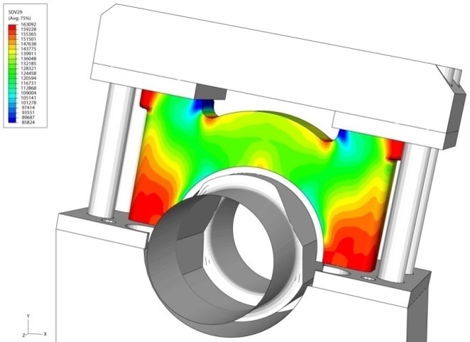
Young's Modulus distribution (MPa). Density Distribution from Compaction/Sintering Analyses.
After compaction, sintering is the next basic step employed for producing PM parts. It consists of heating the powder compact material below the melting point to bond particles and increase the strength of PM parts.
To study the creep of powder due to diffusional mass transport during sintering on the interparticle contacts, McMeeking and Kuhn proposed a macroscopic diffusional creep law in which the densification deformation rate is given by:

where μd and Kd are the shear and bulk viscosities. In their approach, the diffusion was assumed to be very rapid on the free surface of the powder particles, so that the critical phenomenon was mass transport on the interparticle boundary. In these macroscopic continuum models, the microscopic diffusional forces that cause deformation during sintering were equivalent to a macroscopic stress, which is called sintering stress σs . The determination of this effective stress and its dependence on microstructural parameters, especially porosity, has been the focus of many works (Ashby, 1990; Beere, 1975; Skorohod, 1972). It is here function of the relative density ρ , the green relative density ρ0 , the grain size G, and γ the surface energy (Kwon et al., 2004).
The shear and bulk viscosities μd and Kd are averages over the microstructure of the deformation processes within the particles and on interparticle boundaries (German, 1996). Shear and bulk viscosities are common temperature-dependent material parameters used to describe the rheological behavior of wrought materials. However, for porous materials, material parameters continually change as the material densifies during sintering. Therefore, viscosity values measured from porous materials include this density effect and are thus called apparent viscosities. For a given temperature and density, the response of a porous body to strain rate to stress is linear. Therefore, the linearity of the viscous response of the porous body is maintained even though the apparent viscosity changes with density. Finally, the grain growth evolution under pressureless sintering can be written as (Kwon et al., 2004):

where k0 is a material constant, QG the activation energy, and R the gas constant.
Fatigue Modeling
To predict the fatigue life of powder metal alloys, CAVS researchers use a MultiStage Fatigue (MSF) model. Since PM alloys have similar microstructures, inclusions and defects, the model framework is general enough to accurately capture the fatigue behavior of various PM alloys. Initially developed for aluminum cast alloys, the MSF model has undergone minor revisions to account for the porosity degradation of the elastic modulus and void coalescence, as it relates more directly to the nearest neighbor distance.
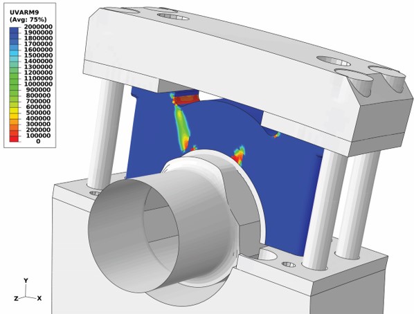
Number of cycles NINC for incubation at a shaft load of 23,000 lbs.
The high-fidelity MSF model predicts the amount of fatigue cycling required to cause the appearance of a measurable crack, with the crack size as a function of loading cycles. The model incorporates microstructural features for fatigue life predictions for incubation, microstructurally small crack growth and long crack growth stages in both high cycle and low cycle regimes. The microstructure-based MSF model incorporates different microstructural discontinuities effect, like pores and inclusions, on physical damage progression.
- Crack incubation (INC)
- Microstructurally small crack (MSC) and physically small crack (PSC) growth
- Long crack (LC) growth
The total fatigue life is decomposed into the cumulative number of cycles spent in several consecutive stages, demonstrated by the following:

where NINC is the number of cycles to incubate a crack at a micronotch that includes the nucleation of crack-like damage and early crack propagation through the region of the micronotch root influence; NMSC is the number of cycles required for propagation of a microstructurally small crack with the crack length a . The crack range, ai < a < kDCS, with the DCS defined as the dendrite cell size, and k as the non-dimensional factor that is representative of a saturation limit for the encountering of a 3-D crack front with sets of microstructural discontinuities. The value NLC is the number of cycles required for LC propagation for crack length a > (10–20) DCS , depending on the amplitude of loading and the corresponding extent of microplasticity ahead of the crack tip. This stage of crack extension is commonly characterized using standard fatigue crack growth experiments, da/dN versus ΔK. Finally NTotal is the total fatigue life.
- Bolt pre-loading: a pre-loading torque of 60 lbf·ft torque is applied to each of the four vertical bolts
- Initial shaft loading: a minimum load of 1,000 lbs is applied upward on the shaft
- Shaft loading: the maximum load 23,000 lbs is linearly applied upward on the shaft
The fatigue life using the MSF model was calculated in the ‘shaft loading’ step analysis only.
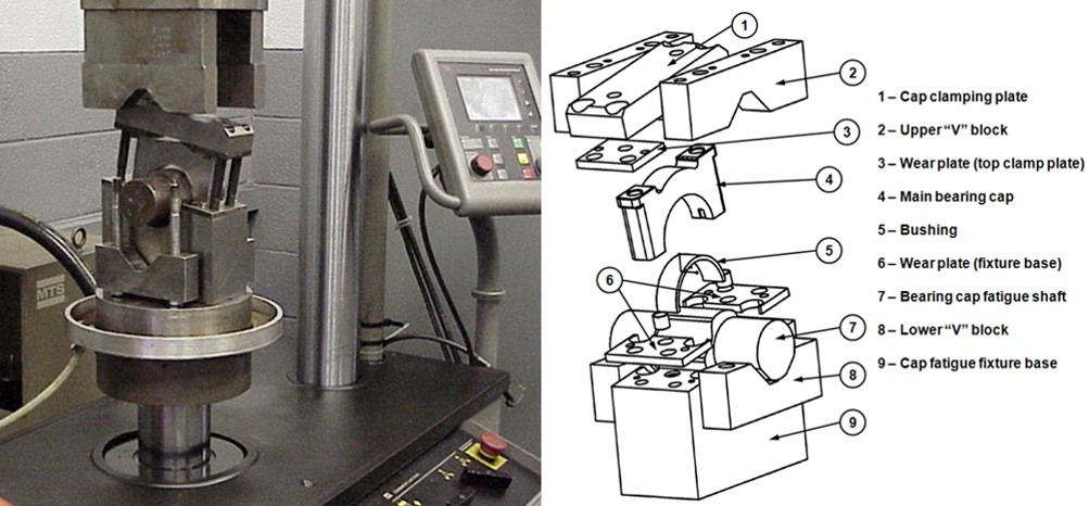
View of the Metaldyne MBC fatigue fixture used for tests
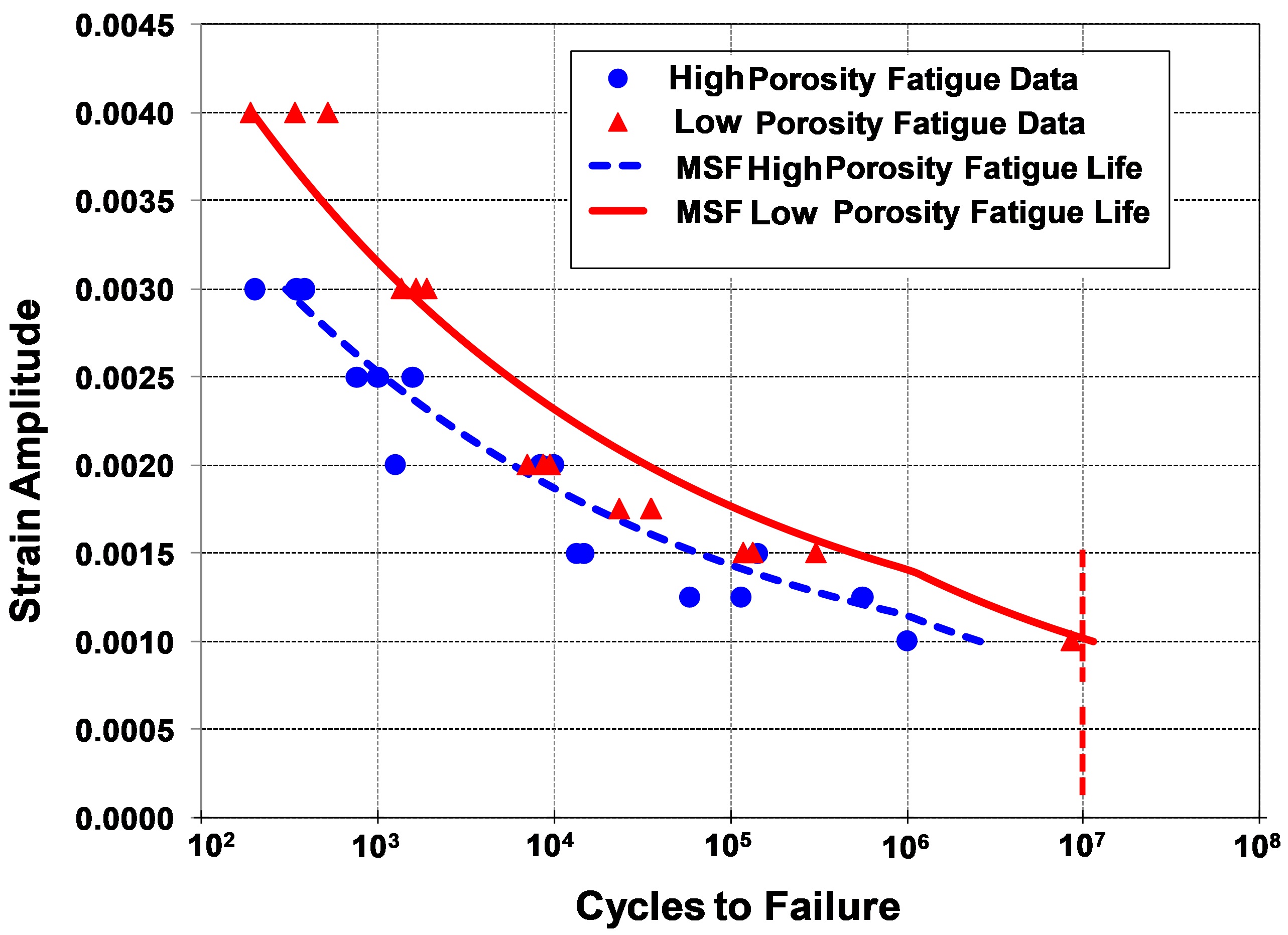
Strain Amplitude vs. Cycle to failure curves for the lower and higher bounds.
To predict the fatigue life of the MBC, the fatigue fixture was modeled using Abaqus/Standard. The density distribution was mapped from the PM compaction process analysis, specifically from the springback analysis, since the density variation during sintering was very small (0.2-0.3%) for the FC-0208 iron-based powder. The Young’s modulus at each material point of the MBC is calculated within a material subroutine UMAT as a function of the porosity.
References
- DiMaggio, F.L. and I.S. Sandler, “Material Models for Granular Soils”, Journal of Engineering Mechanics”, ASCE, 1971, Vol. 97, EM3, pp. 935–950.
- German, R.M., Sintering Theory and Practice, Wiley and Sons, 1996.
- Kraft, T., and H. Riedel, “Numerical simulation of die compaction and sintering”, Powder Metallurgy, 2002, Vol. 45, No. 3, pp. 227–231.
- Kwon, Y.S., Y. Wu, P. Suri, and R.M. German, “Simulation of the Sintering Densification and Shrinkage Behavior of Powder Injection Molded 17-4PH Stainless Steel,” Metal. Mater. Trans., 2004, Vol. 35 A, No. 1, pp. 257–263.
- McMeeking, R.M., and L.T. Kuhn, “A Diffusional Creep Law for Powder Compacts,” Acta Metallurgica and Materiala, Vol. 40, No. 5, pp. 961–969, 1992
- McDowell, D.L., K. Gall, M.F. Horstemeyer, and J. Fan, “Microstructure-Based Fatigue Modeling of Cast A356-T6 Alloy,” Engineering Fracture Mechanics, Vol. 70, pp.49–80, 2003.
- Xue, Y., C.L. Burton, M.F. Horstemeyer, and D.L. McDowell, “Multistage Fatigue Modeling of Cast A356-T6 and A380-F Aluminum Alloys,” Metallurgical and Materials Transactions B, Vol. 38, pp. 601-606, 2007.