
Integrated Computational Materials Engineering (ICME)
Three-Point Bending Behavior of a ZEK100 Mg Alloy at Room Temperature
Abstract
Three-point bending and tensile tests were performed on rare
earth containing ZEK100 at room temperature and various displacement rates
(1.0, 5.0, 10.0, 20.0 and 50.0 mm/min). The bend was either parallel to the
rolling direction (RD specimens) or the transverse direction (TD specimens).
The TD specimens presented higher bendability than the RD specimens. For the TD
specimens, fracture did not occur at low displacement rates of 1.0, 5.0 and
10.0 mm/min, but occurred at 20.0 and 50.0 mm/min. Fracture occurred in the RD
specimens at all the displacement rates. Cracks were observed in both the
compression zone and the tension zone (Fig. 1). Tensile tests in the RD and the
TD show that the ductility in the TD is about three times as much as in the RD,
leading to the better bendability in the RD specimens. The initial texture was
examined by X-ray diffraction (XRD) and the results show that the (0001) basal
texture was weakened and spread along the TD due to the addition of the rare
earth elements. In-situ electron backscatter diffraction (EBSD) analysis was
performed when the specimen was being bent, and the results show that
{1012}〈1011〉 twinning was activated in both the compression zone and the
tension zone, different from highly textured AZ31 sheets. Our results indicate
that the ZEK100 Mg alloy still presents anisotropy in the tensile properties
and in the bending behavior, despite the weakened basal texture.
Author(s): Imran Aslam, Bin Li, Zackery McClelland, Stephen J.
Horstemeyer, Quancang Ma, Paul T. Wang, Mark F. Horstemeyer
Corresponding Author: Imran Aslam
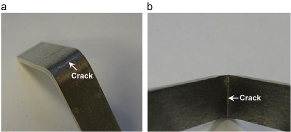
Figure 1. Fracture surface of the (a) tension zone and (b) compression zone. It can be observed that cracks are present in both the tension and compression zones.
Material Used
The material used in this work is ZEK100 (1.0% Zn–0.5% Zr–0.3% RE, and the balance is Mg). The rare earth elements are cesium and lanthanum. More details about the microstructure and texture of this sheet metal can be found in the article[1] published by the Agnew Research Group.
Experimental Method
The as-rolled sheet has a thickness of 1.4 mm. Strips with a dimension of 67
(l) x 6(w) x 1.4 (t) mm3 were sheared from the as-rolled sheet for three-point
bending tests. No heat treatment was conducted before bending. The bending
tests were performed on an Instron 5882, and the span distance was 15 mm. To
study the strain rate sensitivity of three-point bending, various displacement
rates of 1.0, 5.0, 10.0, 20.0 and 50.0 mm/min were used. The bending tests were
carried out either along the rolling direction (RD) or the transverse direction
(TD). A specimen with the bend parallel to the rolling direction (RD) is
designated as the “RD specimen”, and a specimen with the bend parallel to the
TD is designated as the “TD specimen”.
To study microstructure and texture evolution during three-point bending,
electron backscatter diffraction (EBSD) was conducted. Since the as-rolled
sheet experienced large plastic deformation during rolling, meaningful data
cannot be obtained from the as-rolled specimens. To perform EBSD, one of the
specimens was annealed at 300 1C for 1 h inside a furnace filled with inert
argon gas. In-situ EBSD was then conducted on the annealed specimen with a
specially designed, in-house fixture that enables EBSD scans on a specimen that
is being deformed[2].
In conventional EBSD, scans are performed when a
specimen is unloaded after deformation. The in-situ capability in this work
makes it possible to scan the specimens during bending, i.e., without being
unloaded, to examine the microstructure and texture evolution during
deformation. The EBSD scans were conducted through the thickness of the sheet
specimens using a Zeiss Supra 40 Field Emission Gun Scanning Electron
Microscope (FEG-SEM) equipped with an EDAX Hikari EBSD detection system. The
through thickness cross section of the annealed specimen was metallographically
polished and then electropolished using a Struers electropolisher and the
standard C1 Struers electrolyte (160 mg sodium thiocyanate, 800 ml ethanol,80
ml ethylene glycol monobutyl ether, and 20 ml distilled water). EBSD scans were
performed at two different locations: above and below the neutral axis, i.e.,
the compression zone and the tension zone, respectively, and with a step size
of 0.35 mm. The initial macrotexture of the as-rolled ZEK100 sheet was examined
by X-ray diffraction (XRD), using a Regaku SmartLab X-ray diffractometer with a
Cu-Kα radiation source, 40 kV operating voltage, and a 30 mA current.
To examine the anisotropy in the mechanical properties of the as-rolled sheet,
tensile tests were performed along the RD and the TD direction at RT. Dog-bone
specimens were machined with a gauge length 25.4 mm. Various displacement rates
were used in the tensile tests: 1.0, 5.0, 10.0, 20.0 and 50.0 mm/min.
Results
The grain structure of the annealed specimen is shown in Fig. 2. The grain size is about 10 um. Grain growth occurred during annealing, so the initial grain size of the as-rolled sheet should be smaller. The initial XRD texture of the as-rolled sheet is shown in Fig. 3. Indeed, the initial texture is randomized to a certain extent due to the addition of the rare earth elements. Compared to the strong (0001) basal pole of as-rolled AZ31 Mg alloys, the ZEK100 presents split two intensity maxima off the center, but the intensity of the basal pole is mostly distributed along the TD. Also, the intensity of the basal texture is weaker. In contrast, the {1010} prismatic planes still present a strong pole along the RD.
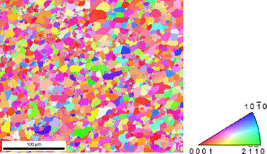
Figure 2. EBSD IPF map of the initial microstructure of the annealed ZEK100 RD specimen. The average grain size is about 10 um.
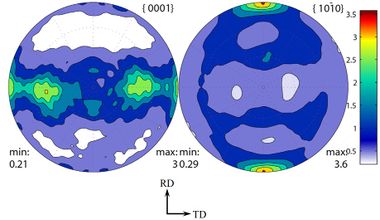
Figure 3. Pole figure of the as-rolled ZEK100 measured by XRD. The sheet does not exhibit strong basal texture.
The three-point bending results of the RD specimens are shown in Fig. 4. For the three relatively low displacement rates, i.e., 1.0, 5.0 and 10.0 mm/min, no specimen failed and the specimens were bent into the fixture with a large bending angle (see Table 1). At faster displacement rates, i.e., 20.0 and 50.0 mm/min, the specimens failed.
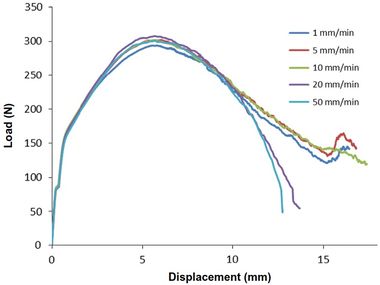
Figure 4. Three-point bending results of the RD specimens at different displacement rates. The specimens at the higher displacement rates failed but did not crack at lower rates
In contrast to the RD specimens, all the TD specimens failed in the three-point bending tests at all the displacement rates in our experiments. As shown in Fig. 5, the displacement to failure increases as the displacement rate decreases, indicating that the bending angle before failure increases as the displacement rate decreases.
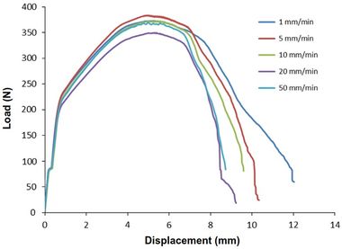
Figure 5. Three-point bending results of the TD specimens at different displacement rates. All the TD specimens failed, but the displacement to failure increases as the displacement rate decreases.
The fracture mode of the specimens that failed in the
bending tests was examined visually. Cracks appear on the top and the bottom
surfaces (as shown in Fig. 1), indicating that cracks were initiated in both
the tension zone and the compression zone.
The fracture mode is different from as-rolled AZ31 Mg sheets in which cracks
are preferentially initiated in the tension zone, but not in the compression
zone. The bending angles of the RD and the TD specimens are shown in Tables 1
and 2, respectively. For those specimens that did not fail, the springback
angle was measured as well and is shown in Table 1. For the RD specimens that
did not fail, no significant difference in the bending angle and the springback
angle is observed, indicating that at these displacement rates, the bending
behavior is relatively insensitive to the strain rate. However, as the
displacement rate further increases to 20.0 and 50.0 mm/min, the bending angle
at which the specimen failed decreases. For the TD specimens, a negative strain
rate sensitivity in the bending angle can be observed, i.e., as the
displacement rate increases, the bending angle decreases.
Table 1
Bend and springback angles of the RD specimens.
| Displacement Rate(mm/min) | 1.0 | 5.0 | 10.0 | 20.0 | 50.0 |
|---|---|---|---|---|---|
| Bending angle (deg) | 148.2 | 149.6 | 151.4 | 132.6 | 128.5 |
| Springback angle (deg) | 15.6 | 16.1 | 15.5 |
Table 2
Bending angles of the TD specimens.
| Displacement Rate (mm/min) | 1.0 | 5.0 | 10.0 | 20.0 | 50.0 |
|---|---|---|---|---|---|
| Bending angle (deg) | 121.4 | 110.5 | 105.4 | 104.1 | 100.3 |
The results of tensile tests in the TD and the RD are shown in Figs. 6 and 7, respectively. Despite the weakened texture, the tensile property still presents anisotropic behavior. In the TD (Fig. 6), the yield stress is about 140 MPa and the ultimate tensile stress (UTS) about 250 MPa and a relatively good ductility can be observed (>14%). The tensile curves in the TD slightly present sigmoidal hardening which is a signature of the activation of the extension twinning [22]. The tensile properties in the TD are insensitive to the displacement rate. In contrast, the yield stress and the UTS in the RD (Fig. 7) present a positive strain rate sensitivity, i.e., both the yield stress and the UTS slightly increase as the displacement rate increases. In the RD, both the yield stress and the UTS are higher than those in the TD, but the ductility is reduced (< 6%). The premature failure at the displacement rate of 20 mm/min is likely due to preexisting defects in the specimen.
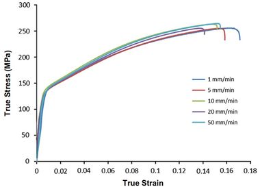
Figure 6. Tension tests in the TD direction at various displacement rates. The ductility, yield strength, and the ultimate strength is insensitive to the displacement rate within the range in this work.
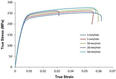
Figure 7. Tension tests in RD direction at various displacement rates. The yield stress and the ultimate strength increase as the displacement rate increases while ductility remains constant.
Acknowledgments
I. Aslam, B. Li, Z. McClelland, S.J. Horstemeyer, Q. Ma, P.T. Wang, and M.F. Horstemeyer gratefully thank the support of Center for Advanced Vehicular Systems, Mississippi State University.
References
1. J. Bohlen, M.R. Nurnberg, J.W. Senn, D. Letzig, S.R.
Agnew (2007). The texture and anisotropy of magnesium–zinc–rare earth alloy
sheets. Acta Materialia, 55, 2101-2112
(https://dx.doi.org/10.1016/j.actamat.2006.11.013).
2. J.C. Baird, B. Li, S. Yazdan Parast, S.J. Horstemeyer, L.G. Hector Jr., P.T.
Wang, M.F. Horstemeyer (2012). Localized twin bands in sheet bending of a
magnesium alloy. Scripta Materialia, 67, 471-474 (https://dx.doi.org/10.1016/j.scriptamat.2012.06.007).