
Integrated Computational Materials Engineering (ICME)
A Goal-Oriented, Inverse Decision-Based Design Method for Multi-Component Product Design
Author(s): Tate R. Fonville, Anand B. Nellippallil, Mark F. Horstemeyer, Janet K. Allen, Farrokh Mistree Corresponding Author: Janet K. Allen
Abstract
We design two components of an American football helmet (composite shell and foam liner) to illustrate the efficacy of a goal-oriented, inverse decision-based design method for multi-component product design. The method is goal-oriented because we first identify the end performance goals for the helmet: to dissipate impact energy, mitigate stress waves, and minimize system weight. We arrange the components in the order that they receive impact energy and then find satisficing solutions for the foam liner that achieve the system-level goals as close as possible, and then we adjust the targets for the composite shell to reduce the system weight without a substantial loss in performance. In our method, we use the Concept Exploration Framework to systematically gather information about each component, and the compromise Decision Support Problem to generate satisficing solutions under uncertainty. Finally, we verify our design decisions with Finite Element Analysis. Although the results are interesting, our focus is to establish the efficacy of the inverse method for the design of an American football helmet.Methodology
In this work, we demonstrate the design of two American football helmet components to establish the efficacy of a goal-oriented, inverse decision-based design method for multi-component product design. The method shown in Figure 1 can be broken up into four steps. The first step is to establish a forward flow of information that links each component to the system-level goals in a consistent way. To establish the “forward modeling and information flow” (shown by the thick blue arrow) we track the energy transferred from a helmet impact, through the composite shell, through the foam liner, and then into the player’s head. The green dashed arrow represents soft information about a component, to be determined in the design analysis. Solid green arrows represent our known design information, or “hard information.” The foam liner and composite shell differ greatly in form and function, however, and must be represented in such a way that ensures a proper flow of information. To do this, we create polynomial response surface metamodels that describe the system-level goals in terms of the individual component design variables. We identified three system-level goals, namely, internal energy, system weight, and impulse where we desire to maximize the first goal and minimize the last two. With a proper forward flow of information, we can find satisficing solutions for the first component (foam liner), and then pass hard information back to design the next component (composite shell) in an inverse fashion. In Step 2, we use the Concept Exploration Framework (CEF) [1] (Figure 2) to systematically gather information about a helmet component, and then identify design alternatives to explore and find satisficing design solutions under uncertainty. We then use the compromise Decision Support Problem (cDSP) [2] to find satisficing solutions for the foam liner design variables that achieve the 3 system-level goals as close as possible. The design variables selected to describe the liner sub-system were foam depth (D), Area Ratio (AR), foam density (rho), and impacting velocity (V). We use ternary plots to visualize the solution spaces for each component and make decisions. After selecting a satisficing alternative, we verify the design decisions with Finite Element Analysis (FEA). In Step 3, we pass the new "hard" information back to design the composite shell in a similar fashion as in Step 2, but with respect to modified design goals, constraints, and targets. The design variables selected to describe the composite shell sub-system were shell thickness (t) and shell density (rho). In Step 4 we verify all design solutions with FEA.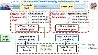
Figure 1.The four steps required to design two helmet components with the goal-oriented, inverse decision-based design method. (click on the image to enlarge).
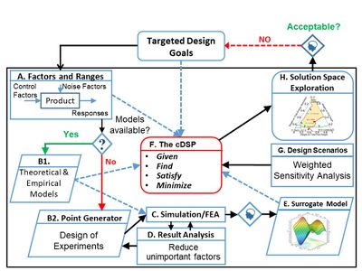
Figure 2.The generic Concept Exploration Framework (CEF) for collecting and managing design information. (click on the image to enlarge).
Material Model
Composite shell material was modeled as "elastic-plastic" for the finite element analysis using material data provided by the manufacturer. Composite shell (RTP 101 CC through 109 CC) material data can be downloaded from the manufacturer: RTP 100 Series Material DataThe polyurethane foam liner was modeled as "Low Density Foam" with density ranging from 7.99*10-11 to 8.43*10-11 (tonne⋅mm-3). The stress strain behavior was imported from quasistatic (0.1 s-1) and high rate (600 s-1) compression tests. The polyurethane foam used in this work is available from the manufacturer: SunMate Cushions
Input Data
To execute the cDSP, four polynomial response models were created that describe the shell and foam liner design variables in terms of the system-level goals. From Step 2 in Figure 1, the polynomial response models for the foam liner are:Internal energy (IE) as a function of depth (D), AR, density (rho), and velocity (V):
IE(D, AR, rho, V) = -68.08173 + 178.7402 * D + 4.544444 * AR + 0.3706196 * rho + 14.87528 * V
Weight (Wt) as a function of depth (D), AR, and density (rho):Wt(D, AR, rho) = 0.028208 + 1.1566 * D + 0.062556 * AR + 0.000723 * rho
Impulse (Imp) as a function of depth (D), AR, density (rho), and velocity (V):Imp(D, AR, rho, V) = 5.15542 - 28.8714 * D - 2.86444 * AR - 0.0910578 * rho + 9.65291 * V
Compression (C) as a function of depth (D), AR, density (rho), and velocity (V):C(D, AR, rho, V) = 0.015383 + 0.3535*D - 0.011584 * AR - 0.0019516 * rho + 0.0059301 * V
Where foam depth (D) ranged from 25.4 - 50.8 mm, Area Ratio (AR) ranged from 0.5 - 1.0, foam density (rho) ranged from 79.9 - 84.3 kg-m-3, and impact velocity (V) ranged from 3.46 - 4.89m-11.From Step 3 in Figure 1, the polynomial response models for the composite shell are: Internal energy (IE) as a function of thickness (t) and density (rho):
IE(t, rho) = 0.0120015318 * rho + 1760.927676 * t - 0.3183868502 * t * rho + 38.14990639 - 208262.5 * t2 - 4.43324515 * 10 -6) * rho2
Weight (Wt) as a function of thickness (t) and density (rho):Wt(t, rho) = 3.2817108 * 10-6 * rho + 10.02042 * t + 0.033070678 * t * rho + 0.083487294 - 1670.0701 * t2 + 4.9352724 * 10-22 * rho2
Impulse (Imp) as a function of thickness (t) and density (rho):Imp(t, rho) = -0.003511421371 * rho + 1245.756881 * t - 0.04013761468 * t * rho + 42.14854726 - 151250 * t2 + 1.631393298 * 10-6 * rho2
Compression (C) as a function of thickness (t) and density (rho):C(t, rho) = 0.032028 - 1.2323 * t - 5.414 * 10 -6* rho
Results
We show the solution space for the foam liner with the ternary plot in Figure 3 where the green region contains 8 satisficing design alternatives. Likewise, we show the solution space for the composite shell with the ternary plot in Figure 4 where the green region contains 18 satisficing design alternatives. The best alternatives where selected for further verification with FEA .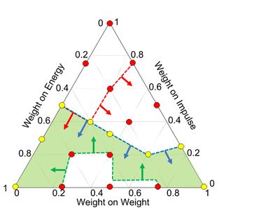
Figure 3.Satisficing solution region for the foam liner showing 8 satisficing design points (Yellow) and 11 non-satisficing points (red). (click on the image to enlarge).
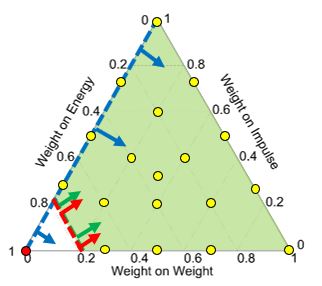
Figure 4.Satisficing solution region for the composite shell showing 18 satisficing design points (yellow) and 1 non-satisficing point (red). (click on the image to enlarge).
Acknowledements
JKA and FM gratefully acknowledge financial support from the John and Mary Moore Chairs and L.A. Comp Chair respectively at the University of Oklahoma. TF and MFH thank the Center for Advanced Vehicular Systems (CAVS) at Mississippi State University for supporting this effort.- ↑ Nellippallil, A. B., Rangaraj, V., Gautham, B. P., Singh, A. K., Allen, J. K., and Mistree, F., 2018, "An Inverse, Decision-Based Design Method for Integrated Design Exploration of Materials, Products and Manufacturing Processes," Journal of Mechanical Design, vol. 140, no. 11, pp. 111403.
- ↑ Mistree, F., Hughes, O. F., and Bras, B., 1993, "Compromise Decision Support Problem and the Adaptive Linear Programming Algorithm," Progress in Astronautics and Aeronautics, vol. 150, pp. 251-251.