
×
![Enlarged Image]()
Integrated Computational Materials Engineering (ICME)
Observations and modeling of the small fatigue crack behavior of an extruded AZ61 magnesium alloy (MSU MSF)
Abstract
The objective of this paper is to quantify the microstructurally small fatigue crack growth of an extruded AZ61 magnesium alloy. Fully reversed and interrupted load-controlled tests were conducted on notched specimens that were taken from the material in the longitudinal and transverse orientations with respect to the extrusion direction. In order to measure crack growth, replicas of the notch surface were made using a dual-step silicon-rubber compound at periodic cyclic intervals. By using microscopic analysis of the replica surfaces, crack initiation sites from numerous locations and crack growth rates were deter- mined. A marked acceleration/deceleration was observed to occur in cracks of smaller length scales due to local microheterogeneities consistent with prior observations of small fatigue crack interaction with the native microstructure and texture. Finally, a microstructure-sensitive multistage fatigue model was employed to estimate the observed crack growth behavior and fatigue life with respect to the microstructure with the most notable item being the grain orientation. The crack growth rate and fatigue life estimates are shown to compare well to published findings for pure magnesium single crystal atomistic simulationsMaterials and Experimental Methods
Materials and Experimental Methods The material used for this study was an AZ61 magnesium alloy extruded into an automotive crash rail, as shown in Figure 1. Note in Figure 1b the layout of the transverse specimens. Longitudinal specimens were oriented 90 degrees from the transverse direction or parallel with the extrusion direction. The as-received, air-quenched crash rail was extruded at an average temperature of 500 Celsius with an extrusion exit speed of 1.2 m/min. In order to calculate the initial material microstructure, samples taken from the rail in both longitudinal and transverse orientations were polished, etched, and examined with an optical microscope. Flat dog-bone specimens were machined from the rail in the transverse and longitudinal directions. A notch with a radius of 35 nm was machined into the face of the gauge to a depth of 300 microns. This specimen type is commonly found in literature [1] [2]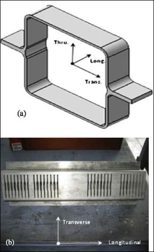
Figure 1. (a) Cross-sectional geometry of the as received, extruded AZ61 magnesium crash rail and (b) transverse specimen layout.
MultiStage Fatigue (MSF) Model
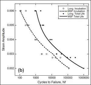
Figure 2. MSF model calibration for longitudinal AZ61 specimens showing the incubation and total life regimes.
The data of this study is used in conjunction with the MultiStage Fatigue (MSF) [3]model to produce calibration constants for extruded AZ61. The MSF model separates fatigue life into three distinct regimes: incubation, microstructurally small crack growth, and long crack growth.
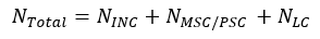
〖N〗_(Totalis the total number of cycles, NINC is the number of cycles required to incubate a fatigue crack near an inclusion, N_(MSC/PSC ) is the number of cycles spent in the microstructurally small/physically small crack regime (typically referred to only as microstructurally small crack growth), and N_LC is the total number of cycles in the long crack regime to failure. Here, failure is defined as complete fracture of the specimen. This study focuses on the crack growth rate for the MSC regime, which is described for the following equation:
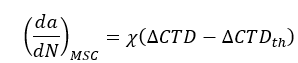
Where χ is a material constant for a given material system, ΔCTD is the three-dimensional crack tip displacement as a function of remote applied load, and ΔCTDth is the crack tip displacement threshold typically taken as the magnitude of the burger's vector for a given material. The crack tip displacement is calculating using the following equation:
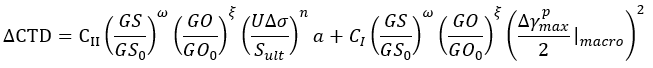
The first half of equation (3) accounts for the cracks under high cycle fatigue while the second half is used to identify the elastic-plastic crack propagation. As shown in equation (3), the second term does not depend on crack length, a. The ratio of grain size to reference grain size of the material (GS/(GS0 )), represents the effect of grain size distribution upon the small crack growth. The ratio of the Taylor factor for the orientation of the grain at the crack tip with the Taylor factor of the typical rolling texture (GO/(GO0)), contains the orientation effects of the microstructure upon the MSC regime. Figure 2 shows the model calibration with respect to experimental fatigue data.
Uncertainty Quantification for MSF Model
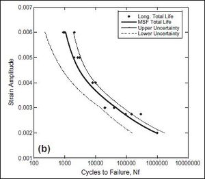
Figure 3. AZ61 Longitudinal total life MSF model correlation with experimental data. The upper and lower uncertainty bounds correspond to a uniform 5% relative uncertainty for each MSF model parameter.
A general uncertainty analysis using the methodology of [4] was performed for preliminary analysis of the effects of experimental uncertainties on performance of the MSF model. A full write-up on the applied uncertainty propagation method can be found on the page MSF Uncertainty.
Due to a lack of experimental data, uncertainty propagation calculations were performed to determine the amount of uncertainty necessary to encompass both the upper and lower bounds of the experimental life values. Figure 3 shows the uncertainty bounding using a 5% relative uncertainty applied to all the modeling parameters for longitudinal specimens; that is, the uncertainty is assumed to be 5% of the calibrated parameter value. Within the context of experimentation, this 5% value generally overestimates the uncertainty from measurements. However, it should be noted that material properties tend to vary ~10% (or more) depending on manufacturing process accuracy.
References
- ↑ Tokaji K, Kamakura M, Ishiizumi Y, Hasegawa N, "Fatigue Behaviour and fracture mechanism of a rolled AZ31 magnesium alloy," Int. J. Fatigue, pp 1217-24 (2014).
- ↑ Lei JF, Wang QJ, Liu YY, Guan SX, Wang ZG, Li D, et al., "Fatigue crack initiation at Nd-rich particles in an Nd containing high temperature titanium alloy," J. Mater. Res, pp 2571-4 (1997).
- ↑ McDowell DL, Gall K, Horstemeyer MF, Fan J, "Microstructure-based fatigue modeling of cast A356-T6 alloy," Eng Fract Mech, pp 49-80 (2003)
- ↑ Coleman, H.W., and Steele, G.W (2010) Experimentation and Uncertainty Analysis for Engineers.