
Integrated Computational Materials Engineering (ICME)
Woodpecker's Hyoid Apparatus
Wave propagation at hyoid bone
Abstract
In this study a woodpecker’s hyoid apparatus was characterized to determine its impact mitigation mechanism using finite element (FE) analysis. The woodpecker’s hyoid apparatus, comprising bone and muscle, has a unique geometry compared to those of other birds. The hyoid starts at the beak tip, surrounds the woodpecker’s skull, and ends at the upper beak/front head intersection while being surrounded by muscle along the whole length. A FE model of the hyoid apparatus was created based on the geometry, microstructure, and mechanical properties garnered from our experimental measurements. We compared the impact mitigation capabilities of the hyoid apparatus with an idealized straight cylinder and a tapered cylinder. The results showed that the hyoid geometry mitigated a greater amount of pressure and impulse compared to the straight or tapered cylinders. The initially applied longitudinal wave lost its strength from attenuation and conversion to transverse shear waves. This is due to the spiral curvature and tapered geometry, which induced lateral displacement in the hyoid bone. The lateral displacement of the bony hyoid induced strains on the adjacent muscle, where the energy dissipated due to the muscle’s viscoelasticity. Quantitatively, as the stress wave traveled from the anterior to the posterior end of the hyoid apparatus, its pressure decreased 75% and the associated impulse decreased 84%. The analysis of the woodpecker’s hyoid apparatus provides a novel perspective on impact mitigation mediated by a spiral-shaped structure and viscoelastic biocomposite.
Methods
Materials and Methods
The hyoid apparatus was dissected from the adult Redbellied Woodpecker, Melanerpes carolinus, which lives in the southern United States. Deceased woodpeckers were obtained from the collections of the Department of Wildlife, Fisheries and Aquaculture (Mississippi State University). The hyoid apparatus, which comprises a bone encapsulated by muscle tissue, was separated from the body of the woodpecker as shown in figure 1(a).
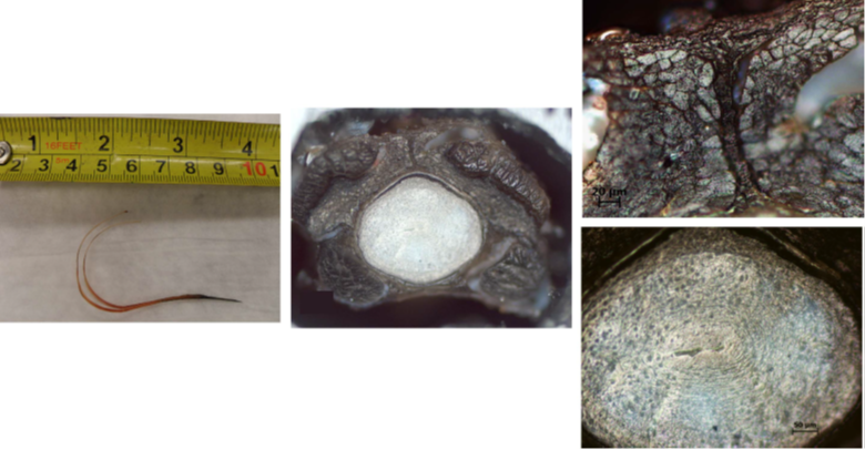
Figure 1. (a) A dissected hyoid apparatus from a red-bellied woodpecker followed by optical microscope images of (b) the cross-section of the hyoid apparatus, (c) the adjacent muscle, and (d) the inner bone.
Experimental Measurements and FE Set Up
Using optical microscopy, we observed the microstructure of the
cross-section. As shown in figure 1(a), the length of the hyoid apparatus of
the red-bellied Woodpecker is about 110 mm. The diameter of the core bone is
approximately 1–3mm and changes gradually from being thick at the tip to being
thin and flexible at the end. In figure 1(b), the muscle is shown to fully
encasing the bone whose diameter is approximately 1mm at the back part of the
hyoid. The thickness of the muscle surrounding the bone is about 0.3 mm. The
muscle tissue was not active but dead and passive and was the only muscle from
the head that was used in our simulations. Figure 1(c) is the muscle, and
figure 1(d) is the bone having a small pore at its center. Nano-indentation
tests were conducted at twelve locations along the hyoid bone. The nanohardness
was quantified as 692.9±170.1 MPa, and the reduced elastic modulus was
17.49±3.17 GPa. The value of reduced elastic modulus of the hyoid bone measured
here is in the range of literature values of bones. The elastic modulus of the
bone part of the hyoid was quantified as 16.13 GPa. Based on the structure
observed under the microscope, the hyoid apparatus FE mesh was built from the
natural structure comprising interior bony material and exterior muscle. In the
simulation, the materials were assumed to be homogeneous and isotropic. For the
bone, the elastic modulus was 16.13 GPa; the density was 1850 kgm−3;
and the Poisson’s ratio was 0.3. Hyperelastic and viscoelastic properties were
used for the muscle with a density of 1100 kgm−3.We employed the
Ogden model and Prony series expansion to describe the passive muscle behavior
and viscoelasticity, respectively. The elastic parameters, μ and α
were 15.6 KPa and 21.4, and the viscoelastic parameters, δ and τ,
were 0.549 and 6.01 s, which were determined from rat muscle. The exterior part
of the muscle was constrained in all of the x, y, and z directions reflecting
that the movement of the muscle was constrained by skull, but the bone was not
assigned boundary conditions since it was adjacent to the muscles. In addition,
we considered that there were no gaps between the bone and muscle as an assumed
perfect adhesion; this is a good assumption since it was very difficult to tear
the muscle away from the bony part in the actual material. As shown in figure
2(a), the impact was applied at the hyoid tip once. The impact pressure was
0.15 MPa, which was calculated from the force of a woodpecker pecking. The
force of pecking was 3.108 N approximately since the mass, m, of the woodpecker
head was measured as 11.1±6 g, and the acceleration, a, of pecking a tree was
280ms−2. The acceleration was calculated from the velocity (7 m
s−1) and time (25 ms) of pecking a tree. Hence, the force applied on
to the woodpecker beaks was 3.108 N. Some part of the force will travel into
the lower and upper beak, and the other portion will go through the hyoid
apparatus. The cross-section of the beak and hyoid shows that the area of the
hyoid is approximately one third of the total area, which consists of the upper
beak, lower beak, and hyoid. The area where the force was applied to the hyoid
is 6.9mm2. Therefore, the applied pressure that arose from the force
over tip area of the bone portion was 0.15 MPa. The model was meshed using
10-node tetrahedral solid elements (C3D10M), which are robust elements for
large deformations and contact problems. To reinsure robustness of the
solution, we used 211, 269 elements for the bone and 203, 823 for the
muscle.
Four regions of interest on the hyoid bone were noted for analyzing the
pressure and deformation. These anatomical regions are the paraglossum,
basihyale, ceratobranchiale, and epibranchiale. In this paper, as shown in
figure 2, they are called the tip, the bone split region, the back, and the
end, respectively. In order to quantify the effects of the hyoid’s tapered
geometry and its curvature, a straight cylinder (SC) and a tapered cylinder
(TC) were also created using the same hyoid apparatus length, the same material
properties, and the same boundary conditions (figures 2(b) and (c)). The data
were analyzed at the four locations corresponding to the four red markings on
the hyoid model. The fourth region of each model was 10mm away from the end to
avoid the boundary effects at the end.
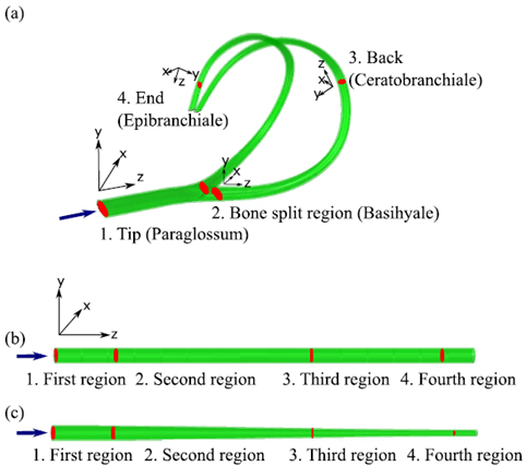
Figure 2. (a) The finite element (FE) geometry of the hyoid apparatus (including bone and muscle throughout the cross section) of a woodpecker. The anatomical terminology indicating the four regions are paraglossum (tip), basihyale (where the bone splits), ceratobranchiale (back), and epibranciale (end), respectively. (b) The straight cylindrical FE geometry and (c) the tapered cylindrical FE geometry (which also include bone and muscle) are also shown with the same distance markers used in the hyoid apparatus. The applied compressive load at the tip of the models (arrow) occurred into the z-direction, and the results were analyzed at the four different locations indicated by the red markings with regard to a current coordinate.
Results
1. Attenuation of pressure in the hyoid apparatus
Nature has many structures that are valuable for engineering-based bio-inspiration. In this context, the spirally shaped hyoid apparatus of the woodpecker is relevant for bio-inspired design of impact mitigating structures. As the first wave passed the four regions (tip, split, back, and end), the pressure and impulse were captured. The impulse is defined as follows:
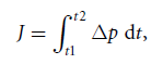
where J is impulse per unit area, t is time, and p is pressure. As shown in
figure 3, the peak pressure decreased 75% from 0.15 MPa to 0.04 MPa as the wave
traveled along the hyoid apparatus from the anterior to the posterior end. The
time duration of the pressure wave also decreased 54% from 26 μs at the tip
to 12 μs at the end region. Reduction of the peak pressure and time duration
led to the impulse decrease of 84% suggesting that the hyoid apparatus has a
great ability to attenuate impact waves. The mechanism that mitigates the
impact pressure is discussed in the next section with regard to transferring a
longitudinal wave into a shear wave and is explained in the context of
comparing the hyoid geometry to the straight cylindrical geometry and the
tapered cylindrical geometry as shown in figure 2.
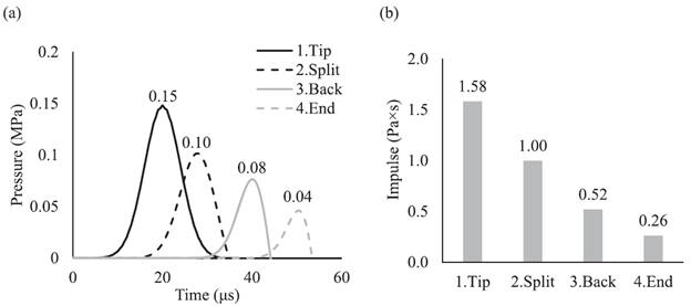
Figure 3. (a) The pressure (of the first wave) versus time history at the four regions of the hyoid model. The number on the top of the curve indicates the peak pressure. (b) The impulse at the four regions of the hyoid model shows a decrease as a function of hyoid length.
2. Comparative study to the straight cylindrical geometry and tapered cylindrical geometry
There are several kinds of waves, but in the interest of this study, we will
discuss longitudinal and transverse waves. In a longitudinal wave,
displacements occur in a parallel direction to the traveling wave; in a
transverse wave, displacements occur in the perpendicular direction to the wave
propagation. Longitudinal waves include sound and compressional elastic waves,
while transverse waves include string waves, membrane waves, electromagnetic
waves, and shear waves. Both longitudinal and transverse waves resulted from
the hyoid, the straight cylindrical, and the tapered cylindrical geometries
following a compressive impact. The longitudinal impulse was calculated from
the normal stress components (S11, S22, and S33), and the transverse impulse
was calculated from shear stress components (S12, S23, and S31).
FE studies showed that the hyoid apparatus was more effective in mitigating a
longitudinal wave when compared to the straight cylindrical or the tapered
cylindrical geometry. Figure 5 shows the longitudinal impulse at the four
different locations of the hyoid apparatus, the straight cylindrical geometry,
and the tapered cylindrical geometry with regard to the axial direction. The
total longitudinal impulse of the pressure wave traversing the hyoid bone
decreased 84% from tip to end. In contrast, at the straight cylindrical
geometry longitudinal impulse decreased 14%, and at the tapered cylindrical
geometry longitudinal impulse increased 45% from the tip to the end because the
effect of the diameter decreases in the cross section that generated greater
stresses (and hence the impulses). Only the hyoid apparatus induced a
longitudinal impulse decrease significantly as the pressure wave traveled.
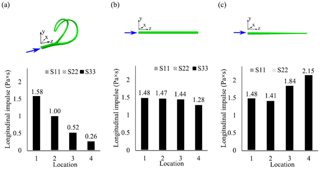
Figure 4. The plots illustrate the longitudinal impulse for each normal stress component of S11, S22, and S33 at the four regions of (a) the hyoid apparatus, (b) straight cylinder, and (c) the tapered cylinder. S33 is in the loading direction, and it follows the axis of the hyoid structure. The wave propagates from the location 1 to location 4.
Reference
1. Nayeon Lee, Lakiesha N. Williams, Hongjoo Rhee, Jun Liao, R. Prabhu, M..F. Horstemeyer "The Role of a Woodpecker’s Hyoid Apparatus for Shock Mitigation," In preparation