
Integrated Computational Materials Engineering (ICME)
Stress Wave Mitigation at Suture Interfaces
Pressure wave propagation at suture complex
Abstract
- We examined the capability of stress wave dissipation at sinusoidal patterned suture interfaces inspired by biological materials.
- A bar with a suture interface attenuated stress waves about 37 % more than a bar with a flat interface.
- Damping is believed to occur by two mechanisms: (i) Wave scattering at the suture interface in which impending compressive waves (S11) converted into flexural (S22) and shear waves (S12), and (ii) energy loss within the strain energy of viscoelastic gap.
- The ratio of the suture height to the bar thickness is the main variable in designing a sinusoidal interface regarding stress dissipation.
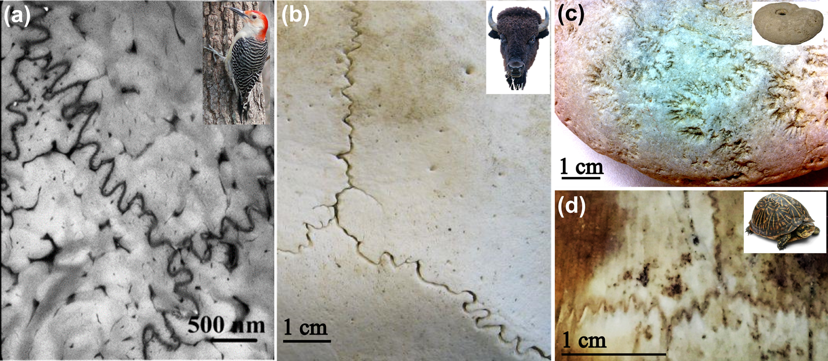
Figure 1. Suture lines in biological materials; (a) suture line shown at the tip of woodpecker beaks (keratin); (b) cranial suture in a bison skull (bone); (c) wavy line in a surface of an ammonoid fossil (calcium carbonate), and; (d) suture at a box turtle (bone).
Methods
An idealized bar with a sutured interface (i.e., sutured bar) and an idealized bar with a flat interface (i.e., unsutured bar) were created and analyzed from two-dimensional Finite Element (FE) analysis in Abaqus/Explicit under dynamic conditions. As shown in Figure 2(a-b), the dimension of the bar was 32 mm×1000 mm, in which one side of the bar was 15 mm×1000 mm with a gap thickness of 2 mm. The wall was treated as an elastic and isotropic material with Young’s modulus E = 8 GPa, Poisson’s ratio ν=0.3, and density = 2000 kg/m3, and those material properties generated a longitudinal wave speed of 2000 m/s. The sutured and unsutured gaps were treated as a viscoelastic material in which the hyperelastic Ogden model was employed with the elastic parameters, µ and a, being 15.6 KPa and 21.4 (Cheng and Gan, 2007), respectively. The impact load was a Gaussian impulse and applied on the left side of the bar as shown in Figure 2(a) and Figure 2(b) with the end nodes, on the same side, fully constrained to the y-direction. The viscoelastic properties were assigned by a Prony series with the viscoelastic parameters, d and t, being 0.549 and 6.01s, respectively, which were determined from a rat muscle study (Bosboom et al., 2001). ). For meshing, a plane stress 4-noded element (CPS4R) was used, and the approximate element size was 0.5 mm generating about 100,000 number of elements in the 2D bar. Then, a parametric study was performed to understand the dependence of suture geometric variables and the external impact load. The seven variables were; (1) suture waviness, (2) Rsuture (ratio of the suture height to the entire bar thickness), (3) suture gap thickness, (4) elastic modulus of the wall, (5) geometry of the bar boundary walls, (6) amplitude of external impact load, and (7) impact duration, which are illustrated in Figure 3. The detail of the experimental case is described in Figure 3. While examining one variable, the other variables were fixed.
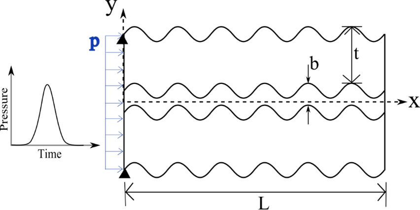
Figure 2a. Idealized two-dimensional bar with a suture interface of gap thickness of b. The dimension of the bar is L = 1000 mm, t = 15 mm, and b = 2 mm. The pressure initiated on the left side of the bar.
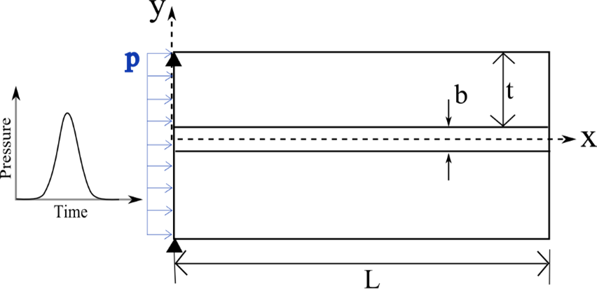
Figure 2b. Schematic of an idealized bar with a flat interface.
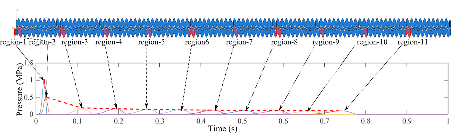
Figure 2c. Following an initial impact pressure applied in Region 1, the pressure data were recorded at the eleven regions indicated by the red regions in the bar. Then, the peak pressures were connected by the red dotted line in the graph. As the pressure wave propagated in the bar, the peak pressure decreased.
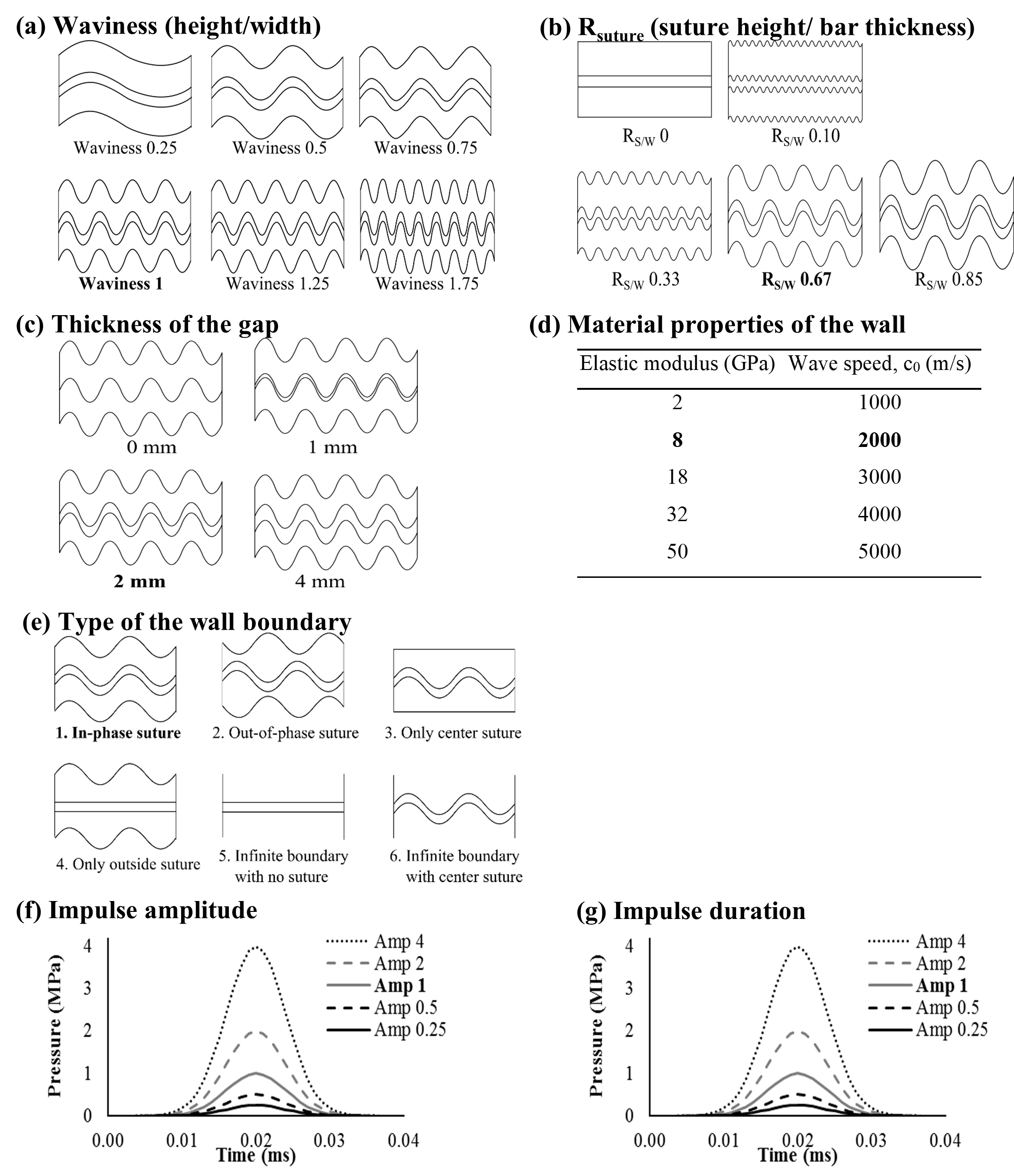
Figure 3. Seven variables influencing the stress wave mitigation; (a) Suture waviness (ratio of suture height to suture period), (b) Rsuture, the ratio of the suture height to the bar thickness, (c) Thickness of the gap, (d) Material properties of the elastic wall, (e) Type of boundary, (f) Amplitude of the impact, and (g) Impact duration. The default values are in bold font.
Results
FE simulations were carried out by applying external mechanical loads to
produce a stress wave that propagated in a continuum media. We examined the
damping capability of suture interfaces by comparing to an unsutured interface
bar. Then, the variables of the suture interfaces such as the geometric
variations and boundary conditions were assessed by their influence on the
stress wave mitigation (pressure reduction of the traveling wave within the
bar).
3.1. Dissipation of stress waves in the suture interface
A sutured interface was able to reduce the stress wave effectively compared to
an unsutured interface. Figure 4 shows the peak pressure decay in the sutured
compared to an unsutured bar. The initial load was 1 MPa, and the peak pressure
when the stress wave reached the end of the bar was 0.47 MPa for the unsutured
bar and 0.1 MPa at the sutured bar. While 53 % of the initial pressure
dissipated while the pressure wave traveled the unsutured bar, 90 % of the
initial pressure dissipated at the sutured bar. The sutured bar pressure was
79% less than that of the unsutured bar over the bar length used in this study.
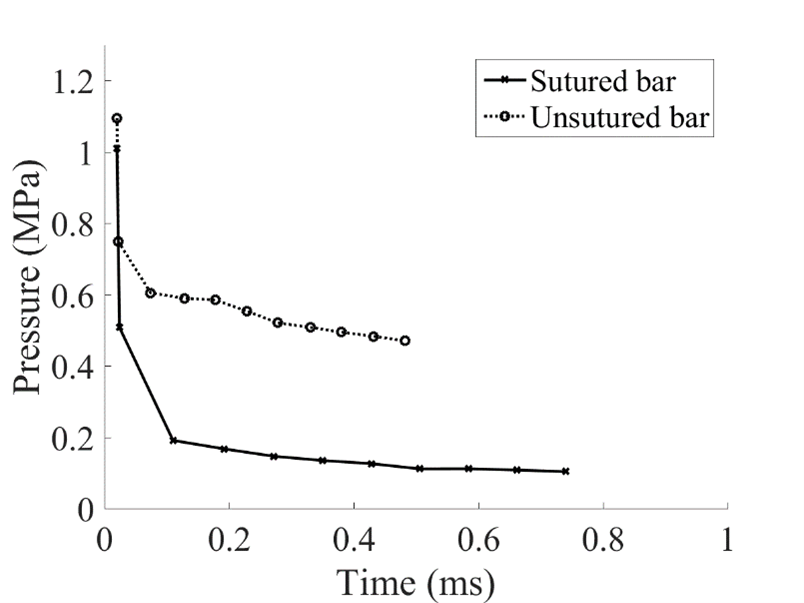
Figure 4. Comparison of pressure recorded along the sutured bar and unsutured bar. Each point represents the peak pressure at the eleven regions. The initial impact was 1 MPa, and the pressure when stress waves reached to the end was 0.47 MPa for the unsutured bar and 0.1 MPa for the sutured bar.
There were two mechanisms associated with the sutured bar for stress wave
mitigation as compared to the unsutured bar. First, stress wave scattering
occurred at the boundary of the sutured bar, in which compressive waves (S11)
were converted into shear waves (S12) and into orthogonal flexural waves (S22).
From a wave perspective, there are two basic types of wave motion for
mechanical waves: longitudinal waves and shear waves (also called transverse
waves). Displacements in longitudinal waves occur in a parallel direction to
the wave propagation, and in transverse waves, displacements occur in a
perpendicular direction (Graff, 1975). The waves related to S11 and S22 are
longitudinal waves, and the waves related to S12 are shear waves.
Wave scattering is an interaction of waves with a boundary or obstacles in a
medium resulting in wave reflection, transmission, or refraction (Brekhovskikh
and Goncharov, 2012). Since the compressive incidence impinged the sinusoidal
interfaces, wave scattering can be considered a reflection at a curved surface
as described in Figure 5. The reflected waves consist of longitudinal and shear
waves with angles of ΘL and ΘS, respectively.
According to DasGupta and Hagedorn (2007), wave scattering at boundaries can be
defined as the following numerical expression. The total wave field can be
represented as the following:
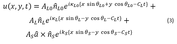
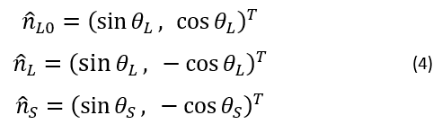
where u is the displacement, t is the time, A is the amplitude, κ is the wave number, and Θ is the angle between the waves. L0, L, and S are the incident waves, reflected longitudinal waves, and reflected shear waves, respectively. The directions of the waves are
Also, the speeds of longitudinal wave and shear wave are
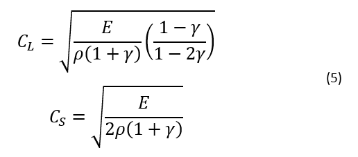
where E is a Young’s modulus, γ is a Poisson ratio, and ρ is a density. For given material properties in this study, CL = 2320.3 m/s and CS = 1240.3 m/s. With an assumption that a reflecting surface is a free surface, then the boundary conditions are as follows:
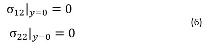
The boundary conditions produce the following relationships:
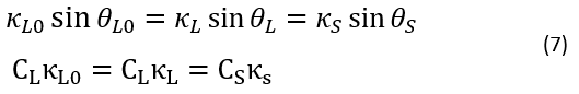
Then,
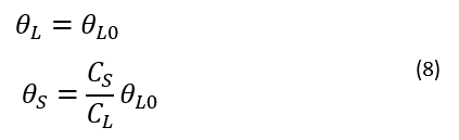
For the given conditions of this study, the angles of the reflected
longitudinal waves are the same as the angles of incident longitudinal waves.
On the other hand, the angles of reflected shear waves are 0.53 times the
angles of the incident longitudinal waves.
As a result of wave scattering at the suture interfaces, the magnitude of S11
decreased, and S12 and S22 increased (Figure 6).The maximum S22 generated in
the sutured bar was 1.58 MPa approximately three times greater than that of the
unsutured bar with S22 equaling 0.54 MPa; the maximum S12 generated in the
sutured bar was 1.59 MPa approximately five times greater than that of the
unsutured bar with S12 equaling 0.29 MPa. Not only does one observe a pressure
decay but also wave dispersion from wave scattering. The wave speed determined
from Eqtn. (5) is 2000 m/s when there are no boundary effects. In the unsutured
bar with boundaries, the wave speed decreased to 1818.18 m/s and arrived at
0.55 ms. Alternatively, in the sutured bar with boundaries, the wave speed
decreased to 1282.05 m/s and arrived at the free end at 0.78 ms. Accordingly,
the sutured bar induced y-direction longitudinal (LE22) and shear strains
(LE12). Figure 7 shows that the sutured bar induced strains in the y-direction
and shear direction but decreased strains in the x-direction.
Figure 8 shows the maximum strain energy density in the sutured and unsutured
bar at Region-2 (near-front region) where the sinusoidal suture began so that
the wave scattering started early. The peak strain energy was 0.09 J in the
sutured bar and 0.03 J in the unsutured bar. Hence, the sutured bar incurred
approximately three times greater strain energy than that of unsutured bar.
Specifically, in the sutured bar, the strain energy was stored in all
directions of xx (17.73 %), yy (45.59), and xy (36.68 %) due to reflected
stress waves, while in the unsutured bar most of the strain energy stored was
only in the xx direction (86.43 %).
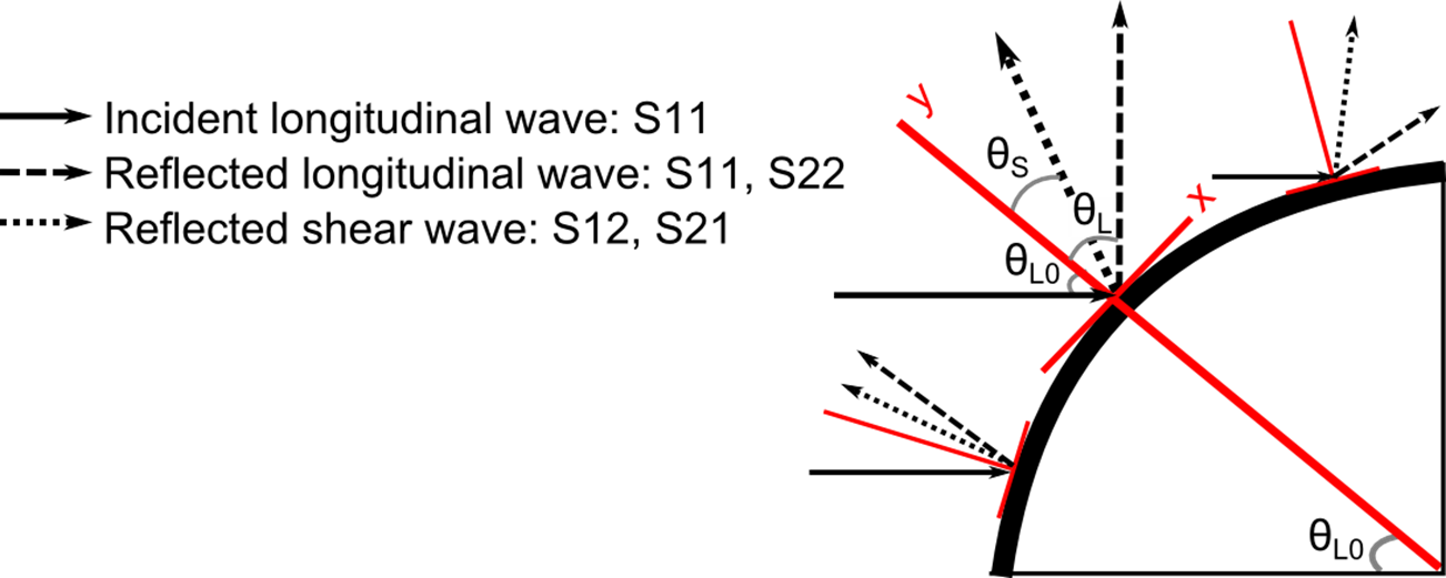
Figure 5. Reflections of compressive incidence waves striking a curved boundary. The incident longitudinal wave with an angle of ΘL0 reflected to a longitudinal wave with an angle of ΘL and a shear wave with an angle of ΘS.
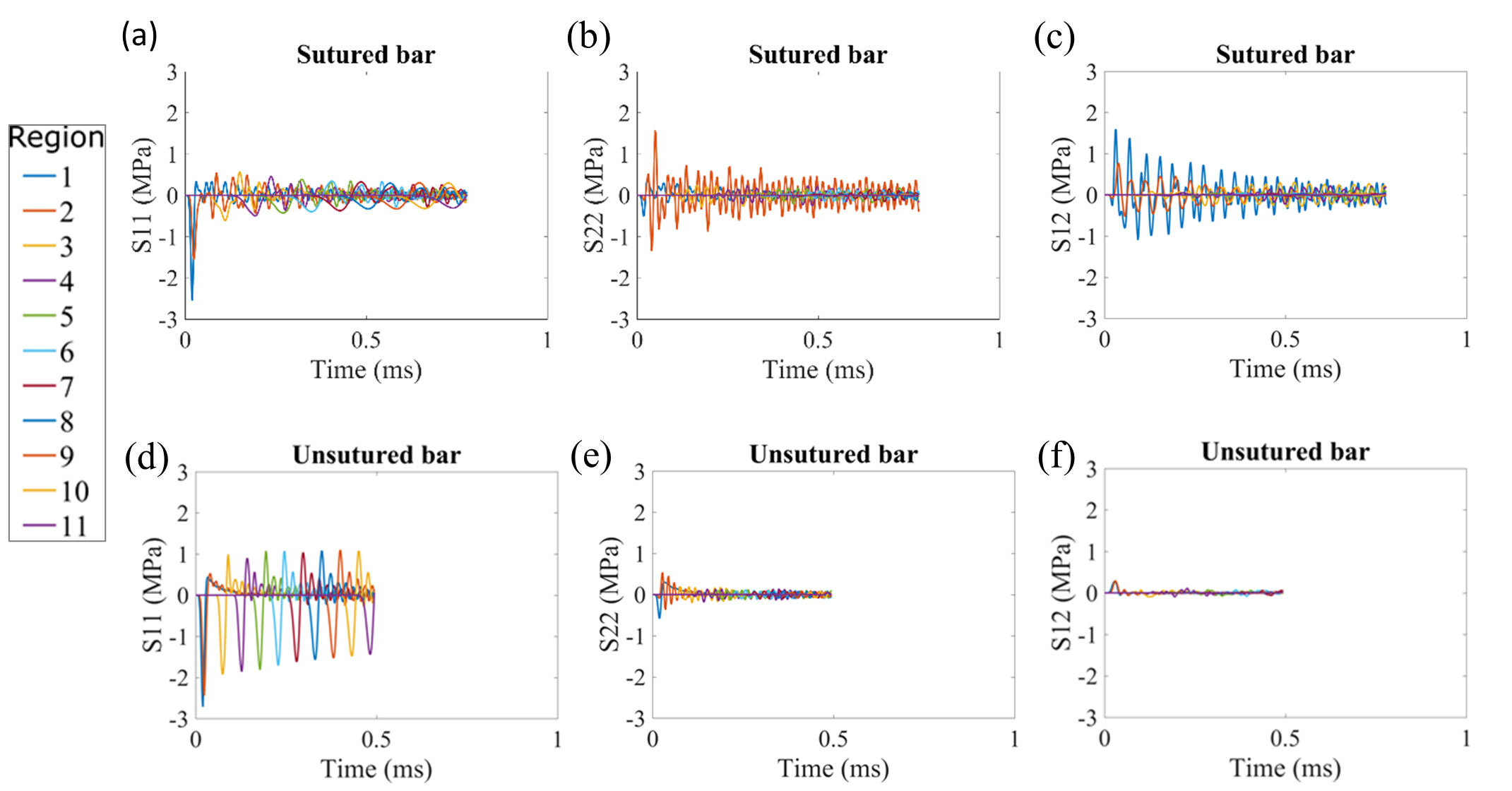
Figure 6. Stress waves shown as a function of time in the eleven regions along the sutured bar illustrating the stress components of (a) S11, (b) S22, (c) S12, and along the unsutured bar also illustrating (d) S11, (e) S22, and (f) S12. The stress waves were plotted until the wave reached the end of the bar. For the sutured bar, the stress wave reached the end at 0.78 ms, and for the unsutured bar, the stress wave reach the end at 0. 55 ms.
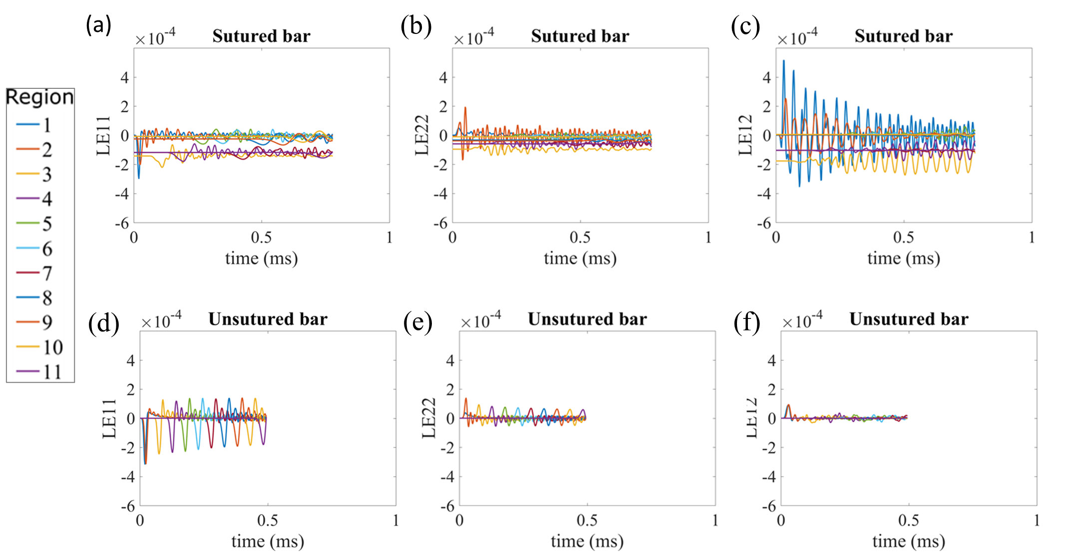
Figure 7. Strain in the eleven regions along the sutured bar for the strain components of (a) LE11, (b) LE22, (c) LE12 and along the unsutured bar for the stress components of (d) LE11, (e) LE22, and (f) LE12.
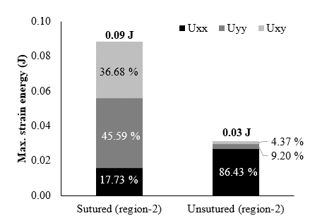
Figure 8. Maximum strain energy density associated with different displacements in the x, y, and z directions for the sutured and unsutured bar in Region 2 (indicated in Figure 2(c)) near the initial impact location. The total strain energy is greater for the sutured bar than that of the unsutured bar because the strain energy to yy and xy direction is much greater at the sutured bar.
Another mechanism that reduced the amplitude of the traveling pressure wave was related to the strain energy being stored in the viscoelastic suture gap. It is common to interleave viscoelastic layers between hard and stiff material to increase the damping of the structure (Berthelot et al., 2008; Cupiał and Nizioł, 1995; Saravanos and Pereira, 1992), and biological materials appear to employ the same strategy. Figure 9 compares the strain energy of the gap between the sutured and unsutured bars. The viscoelastic gap material of the sutured bar allowed for energy dissipation since the strain energy in viscoelastic material is proportional to the damping (Plunkett, 1992).
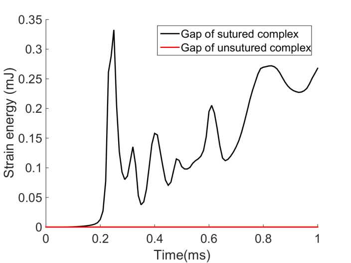
Figure 9. Strain energy occurring at the gap of the sutured bar (black) compared to the unsutured bar (red).
Reference
Lee, N., Williams, L.N., Mun, S., Rhee, H., Prabhu, R., Bhattarai, K.R. and Horstemeyer, M.F., 2017. Stress wave mitigation at suture interfaces. Biomedical Physics & Engineering Express, 3(3), p.035025.