
Integrated Computational Materials Engineering (ICME)
Geometric Effects on Stress Wave Propagation
Abstract
The present study, through finite element simulations, shows the geometric
effects of a bio-inspired solid on pressure and impulse mitigation for an
elastic, plastic, and viscoelastic material. Because of the bio-inspired
geometries, stress wave mitigation became apparent in a non-intuitive manner
such that potential real-world applications in human protective gear designs
are realizable. In nature, there are several toroidal designs that are employed
for mitigating stress waves; examples include the hyoid bone on the back of a
woodpecker’s jaw that extends around the skull to its nose and a ram’s horn.
This study evaluates four different geometries with the same length and same
initial cross-sectional diameter at the impact location in three dimensional
finite element analyses. The geometries in increasing complexity were the
following: 1. a round cylinder; 2. a round cylinder that was tapered to a
point; 3. a round cylinder that was spiraled in a two dimensional plane; and 4.
a round cylinder that was tapered and spiraled in a two dimensional plane. The
results show that the tapered spiral geometry mitigated the greatest amount of
pressure and impulse (approximately 98% mitigation) when compared to the
cylinder regardless of material type (elastic, plastic, and viscoelastic) and
regardless of input pressure signature. The specimen taper effectively
mitigated the stress wave as a result of uniaxial deformational processes and
an induced shear that arose from its geometry. Due to the decreasing
cross-sectional area arising from the taper, the local uniaxial and shear
stresses increased along the specimen length. The spiral induced even greater
shear stresses that help mitigate the stress wave and also induced transverse
displacements at the tip such that minimal wave reflections occurred. This
phenomenon arose although only longitudinal waves were introduced as the
initial Boundary Condition (BC). In nature, when shearing occurs within or
between materials (friction), dissipation usually results helping the
mitigation of the stress wave and is illustrated in this study with the taper
and spiral geometries. The combined taper and spiral optimized stress wave
mitigation in terms of the pressure and impulse, thus providing insight into
the ram’s horn design and woodpecker hyoid designs found in nature.
Author(s): K.L. Johnson, M.W. Trim, M.F. Horstemeyer, N. Lee, L.N. Williams, J.
Liao, H. Rhee, R. Prabhu
Methodology
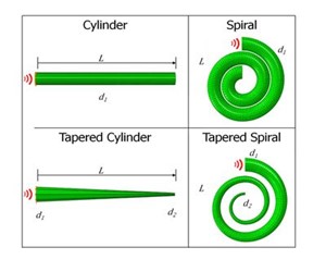
Figure 1. Schematic representation of the four finite element meshes illustrating the four different geometric configurations with the same length (and the same bar diameter where the pressure was applied) used in the analysis.
Fig. 1 depicts the four geometries that were studied along with the load and prescribed boundary conditions. The total length and cross-sectional diameters at the starting end were maintained among the four geometries. The ratio of the large and small-end diameters was also consistent for the tapered geometries. The finite element program ABAQUS/Explicit v6.11 [14], a stress wave dynamics code, was used as the numerical model in this study. To demonstrate material independence, material properties for three different materials were used. The materials are metal (AM30 magnesium denoting a common plastic material), polymer (Polycarbonate denoting a common viscoelastic material), and ceramic (Silicon Carbide (SiC) denoting a common elastic material) were investigated. Post-processing of data was performed using ABAQUS/CAE v6.11 [14]. Pressure and von Mises contour plots were generated when the wave front was at distance 1/3L, 2/3L, and L. Pressure and displacement response histories were generated at a distance of 0.1 m away from the free end to avoid edge effects. The distance corresponded to a rotation of 180 degrees from the free end on the spiraled geometries. The pressure histories were created by averaging the respective output of each node lying on the cross-section at the specified offset from the free end.
Material Model
ABAQUS/Explicit v6.11: Abaqus/Explicit is a finite element analysis software application that employs explicit integration scheme to solve highly nonlinear transient dynamic and quasi-static analyses.
Results
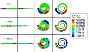
Figure 2. Pressure contour plots in AM30.
Fig. 2 show the pressure contour plots for the cylinder, tapered cylinder,
spiral, and tapered spiral using AM30 material properties when the wave front
is at distance 1/3L, 2/3L, and L. Fig. 2 shows indeed that the tapered cylinder
geometry induced greater hydrostatic and shear stresses as the dynamic wave
propagated towards the smaller end of the bar.
The following conclusions can be made regarding this study:
- A tapered geometry will lower the pressure and impulse due to the convergent boundary and a continually decreasing cross-sectional area such that greater uniaxial stresses and subsequent axial deformation arises. Furthermore, the tapered geometry introduces small shear stresses that also help lower the impulse by removing energy from the initial longitudinal wave.
- A spiral geometry will lower the impulse due to the introduction of shear stresses along the length of the spiral. These shear stresses introduce transverse displacements that help reduce the pressure and impulse.
- When both the tapered and spiral geometry are included in a design, their synergistic effects multiplicatively reduce the pressure and impulse.
- Although different materials admit different wave speeds, this impulse reduction was repeated in the three material types (elastic, plastic, and viscoelastic) and loading conditions.
Figure 3. Movie showing pressure wave behavior in different geometries.