UG_IO SimSys 3D Input/Output Grid Files
Input grids for all UG related routines, such as AFLR3, assume a consistent ordering of the connectivity. Input grids for AFLR3 use the optional reconnection flag, grid boundary condition, and initial normal spacing data if it is included. Output grids from AFLR3 usually include volume element connectivity and typically don't contain any of the optional surface grid information.
SURFACE GRID CONNECTIVITY
The node indices for the
boundary face connectivity must be numbered one through Number_of_Nodes. For
AFLR3, all boundary surface faces on a closed surface should be ordered so that
their normals all point out of or into the surface. This is not required if all
surfaces are simply connected. If they are not and there are areas where more
than two faces share an edge then continuous ordering
must be maintained. Each closed surface may have a different ordering (some may
point out and some in). All nodes must be unique in physical space (a given
coordinate location may not have two or more different node numbers). Also,
each possible node index must correspond to an actual node on the boundary
surface triangulation.
The node connectivity for
boundary surface tria faces is ordered as shown below.

where
inode1 = Surf_Tria_Connectivity[0];
inode2 = Surf_Tria_Connectivity[1];
inode3 = Surf_Tria_Connectivity[2];
Indices for tria faces, itria, are numbered one through Number_of_Trias.
Indices for nodes, inode1, ..., are numbered one through
Number_of_Nodes.
The node connectivity for boundary surface quad faces is ordered as shown below.

where
inode1 = Surf_Quad_Connectivity[0];
inode2 = Surf_Quad_Connectivity[1];
inode3 = Surf_Quad_Connectivity[2];
inode4 = Surf_Quad_Connectivity[3];
Indices for quad faces, iquad, are numbered one through Number_of_Quads.
Indices for nodes, inode1,..., are numbered one
through Number_of_Nodes. Input boundary surface grid quad faces are
typically converted to tria faces.
AFLR3 SURFACE FACE RECONNECTION FLAG
In AFLR3 the reconnection flag for each boundary surface tria face controls reconnection of the surface triangulation during boundary recovery. If the flag is zero then the face can be reconnected with any of its three neighbors. This allows reconnection of the face during boundary recovery. If the flag is positive then the face can not be reconnected with one or more "restricted neighbors" in specified directions. The "restricted neighbors" are specified as follows.
| Reconnection Flag | Restricted Neighbor(s) | ||||
| 0 | |||||
| 1 | itria1 | ||||
| 2 | itria2 | ||||
| 3 | itria1 | itria2 | |||
| 4 | itria3 | ||||
| 5 | itria1 | itria3 | |||
| 6 | itria2 | itria3 | |||
| 7 | itria1 | itria2 | itria3 | ||

If faces itria and itria3
should not be reconnected with each other than the appropriate flag for
boundary face itria would have a value of four. The flag for boundary
face itria4 does not have to be set. AFLR3 will reset the reconnection
flag for neighbor faces so each has compatible flags. Priority is always given
to restricting reconnection whenever the reconnection flag is reset.
For boundary surface quad faces
the reconnection flag is set by AFLR3. The value obtained from the input file
is ignored. Within AFLR3 all quads are converted to trias and the reconnection
flag is set such that the quad edges are preserved.
In general, reconnection of the
surface grid should be allowed wherever possible. AFLR3 will reconnect only if necessary for boundary recovery and if the resulting quality
is within specified limits or better then that of the existing grid. The
resulting volume grids are usually of optimal quality if surface reconnection
is allowed. If part of a surface grid must be connected to another grid with a
prescribed triangulation then limit reconnection only on those faces that must
match up. The default value for the reconnection flag is zero.
AFLR3 SURFACE FACE ID
In AFLR3 the surface ID is used to group boundary surface faces. It defines a "surface". Boundary reconnection between faces on different "surfaces" is restricted (the reconnection flag is automatically set within AFLR3). Surface ID's are also used with grid boundary condition flag (see grid boundary condition flag description). And, surface ID's are used to set grid boundary conditions with the batch/script version of AFLR3.
AFLR3 SURFACE FACE GRID BOUNDARY CONDITION FLAG
In AFLR3 the grid boundary condition flag magnitude identifies special types of surfaces. The grid boundary condition flag is only applicable if boundary-layer or structured-layer grid generation is selected or if there are embedded or transparent surfaces. A "surface" is defined as a group of connected faces with the same boundary id flag. The default value for the grid boundary condition flag is -1. Note that in some cases multiple values of the grid boundary condition flag have the same meaning. The possible values and their implied meaning are listed below.
| Grid Boundary Condition | Description |
| -6 | internal embedded/transparent surface that will be converted to internal/interior/volume faces with BL volume grid |
| -5 | embedded/transparent surface with BL volume grid |
| -1 | standard surface with BL volume grid |
| 0 | standard surface |
| 1 | standard surface |
| 2 | standard surface that intersects the BL region |
| 3 | embedded/transparent surface or source surface that will be converted to source nodes |
| 4 | embedded/transparent surface that intersects the BL region |
| 5 | embedded/transparent surface |
| 6 | internal embedded/transparent surface that will be converted to internal/interior/volume faces |
| 7 | fixed surface that intersects and directly connects to the BL region |
| Grid Boundary Condition | Description |
| -6 | internal embedded/transparent surface that will be converted to internal/interior/volume faces |
| -5 | embedded/transparent surface |
| -1 | standard surface |
| 0 | standard surface |
| 1 | standard surface |
| 2 | standard surface |
| 3 | embedded/transparent surface or source surface that will be converted to source nodes |
| 4 | embedded/transparent surface |
| 5 | embedded/transparent surface |
| 6 | internal embedded/transparent surface that will be converted to internal/interior/volume faces |
| 7 | standard surface |
AFLR3 INITIAL NORMAL SPACING
In AFLR3 the initial normal spacing for boundary-layer elements can be specified as part of an input surface grid. If it is specified then a value must be given for every surface node. Only those values for nodes on a boundary face with a negative grid boundary condition flag will actually be used. The initial normal spacing is only used if the boundary-layer option is selected. The default value for the initial normal spacing is zero.
AFLR3 BOUNDARY-LAYER THICKNESS
In AFLR3 the desired boundary-layer thickness for boundary-layer elements can be specified as part of an input surface grid. If it is specified then a value must be given for every surface node. Only those values for nodes on a boundary face with a negative grid boundary condition flag will actually be used. The boundary-layer thickness is only used if the boundary-layer option is selected. The default value for the boundary-layer thickness is zero.
VOLUME GRID TET ELEMENT CONNECTIVITY
The node connectivity for tet elements is ordered as shown below.

where
inode1 = Vol_Tet_Connectivity[itet][0];
inode2 = Vol_Tet_Connectivity[itet][1];
inode3 = Vol_Tet_Connectivity[itet][2];
inode4 = Vol_Tet_Connectivity[itet][3];
Indices for tet elements, itet, are numbered one through Number_of_Tets,
Indices for nodes, inode1,..., are numbered one through
Number_of_Nodes.
VOLUME GRID FIVE NODE PENT ELEMENT CONNECTIVITY
The node connectivity for five node pent elements is ordered as shown below.

where
inode1 = Vol_Pent5_Connectivity[ipent5][0];
inode2 = Vol_Pent5_Connectivity[ipent5][1];
inode3 = Vol_Pent5_Connectivity[ipent5][2];
inode4 = Vol_Pent5_Connectivity[ipent5][3];
inode5 = Vol_Pent5_Connectivity[ipent5][4];
VOLUME GRID SIX NODE PENT ELEMENT CONNECTIVITY
The node connectivity for six node pent elements is ordered as shown below.

where
inode1 = Vol_Pent6_Connectivity[ipent6][0];
inode2 = Vol_Pent6_Connectivity[ipent6][1];
inode3 = Vol_Pent6_Connectivity[ipent6][2];
inode4 = Vol_Pent6_Connectivity[ipent6][3];
inode5 = Vol_Pent6_Connectivity[ipent6][4];
inode6 = Vol_Pent6_Connectivity[ipent6][5];
Indices for prism (6-noded pent) elements, ipent6, are numbered one through
Number_of_Pents_6, Indices for nodes, inode1,..., are numbered one through
Number_of_Nodes.
VOLUME GRID HEX ELEMENT CONNECTIVITY
The node connectivity for hex elements is ordered as shown below.

where
inode1 = Vol_Hex_Connectivity[ihex][0];
inode2 = Vol_Hex_Connectivity[ihex][1];
inode3 = Vol_Hex_Connectivity[ihex][2];
inode4 = Vol_Hex_Connectivity[ihex][3];
inode5 = Vol_Hex_Connectivity[ihex][4];
inode6 = Vol_Hex_Connectivity[ihex][5];
inode7 = Vol_Hex_Connectivity[ihex][6];
inode8 = Vol_Hex_Connectivity[ihex][7];
Indices for hex elements, ihex, are numbered one through
Number_of_Hexs, Indices for nodes, inode1,..., are numbered one through
Number_of_Hexs.
SPLIT FACE HEX ELEMENT CONNECTIVITY
The ICE option (-ice or m_ice=1)
of AFLR3 generates a grid with a Cartesian core of hex elements
that vary in size based on the background mesh and surface mesh. Size
variations between neighboring hex elements is limited to a factor of two.
Neighboring hex elements of varying size produce split faces. Split quad faces
match only at the outermost corner points and have hanging internal edges and
nodes. Additional information is required in order to create a map of element
neighbors. AFLR outputs this information in the form of a SPLIT type data file
for applications that require an element neighbor map. The SPLIT file contains
a list of hex elements that have split faces. The data for each hex element
with a split face includes the hex element index, the split face index (face),
the four non-matching edge-mid-points (inode1, inode2, inode3, inode4),
and the one non-matching face-mid-points (inode5). See the
SPLIT file type description for more
information.
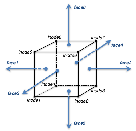
The face index varies from 1 to
6 and its ordering is shown below (face1 is 1, face2 is 2, etc.) The node
indicies shown are defined by the hex element connectivity. Each face consist of four nodes. For example, face 2 is made up of
node indicies inode3, inode2, inode6, and inode7.
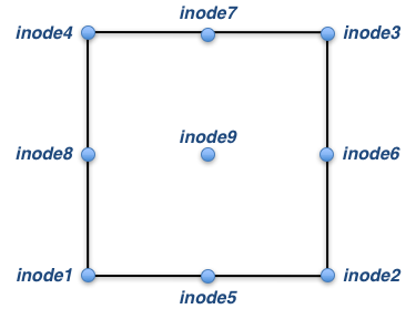
The hanging or non-matching points are numbered relative to a given face of the hex element. The ordering of the four edge-mid-points and one face-mid-point along with the four corner points is shown below. A node index for each of these points is given in the SPLIT file. If any of them do not
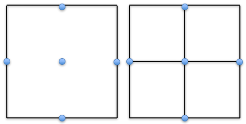
Each split face matches up to either four quad faces of four neighboring hex elements or three to six tria faces of three to six tet elements. No other configurations are possible. If all five mid-points exist then the split face matches four quad faces as shown below.
If four mid-points exist then the split face matches to six tria faces as shown below. Note that the solid line and the dashed line represent the two possible triangulations of the face.
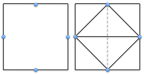
If three mid-points exist then the split face matches to five tria faces as shown below. Note that the solid line and the dashed line represent the two possible triangulations of the face. Also, this configuration can be rotated for four similar configurations.
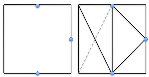
If two mid-points exist then the split face matches to four tria faces in one of the two configurations shown below. The first configuration can be rotated for four similar configurations and the second one shown can be rotated for two similar configurations. Note that the solid line and the dashed line represent the two possible triangulations of the face.
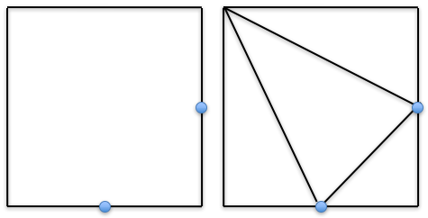
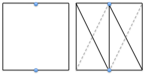
The final possible configuration is for a single mid-point and it matches to three tria faces as shown below. This configuration can also be rotated for four similar configurations.
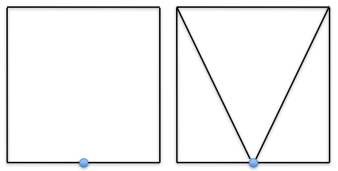
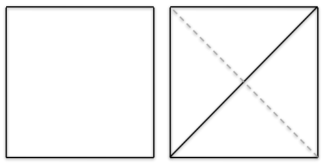
Note that if the hex element is not split, it still may have a hanging edge. Each non-split face matches up to either one quad face of the one neighboring hex element or two tria faces of the two neighboring tet elements. This non-split situation with neighboring tet elements is shown below. Note that the solid line and the dashed line represent the two possible triangulations of the face.