
Integrated Computational Materials Engineering (ICME)
Rolled Homogeneous Armor
Abstract
Undertaken in this work is an investigation of the mechanical response and damage evolution of Rolled Homogeneous Armor (RHA) at different temperatures, stress states, and strain rates. Tension and torsion experiments revealed that torsional loading was more deleterious to ductility when comparing failure equivalent strains. Tests conducted at 300°C in tension and compression showed a reduction in flow stress, as well as the higher elongation to failure as compared to room temperature tests. Also, high strain rate experiments conducted via Hopkinson (Kolsky) bar, showed increased strength, and reduced strain to failure in tension and torsion. Fractography was performed on selected tension and torsion experiments to quantify the number density of nucleated voids during these experiments. A internal state variable (ISV) plasticity/damage model was selected to capture the effects of temperature, strain rate, stress state, and void nucleation for RHA with a single set of parameters. The conclusion of this work is that RHA’s mechanical response is dependent on the applied strain rate, stress state, and temperature and therefore capturing these effects requires modeling which can differentiate the mechanical response with respect to the aforementioned conditions [1].
Materials and Methods
Compressive stress strain curves gathered from experiments and the calibrated response from the ISV/Damage model.
As received half inch thick RHA plates, from Engineer Research and Development Center (ERDC), was utilized for experimentation and analysis. Virgin specimens were cut out of various sections and polished for optical microscopy using Stuers polishing techniques and examined with concern for the initial particle distribution using a Zeiss Optical Microscope. An image analysis code was utilized for gaining particle statistics on the size, area fraction, and nearest neighbor distance. The data was then imported into model calibration software, known as MSU DMG/fit, which allows for routine calibration of material experimental results to the material model. Specimens were extracted by way of conventional machining operations to be used in mechanical testing. For low rate tension and compression testing, an Instron 5869 load frame was utilized with a 50kN load cell for gathering load data, with a 25 mm full scale contact extensometer for gathering strain data. The compression specimens were dimensioned as right cylinders of 10 mm in diameter. For tension, flat dogbone specimens were dimensioned to have a gauge length of 5 mm, width of 2 mm, and thickness of 1 mm to be small enough to allow the same specimen geometry for high rate tests. Tests were conducted at room temperature and at 300°C, using an Instron temperature controlled environmental chamber. Three tests of each criterion were performed and one specimen from each tension test was used for fracture studies. Low rate torsion tests were conducted on an MTS 858 biaxial load frame at room temperature. Axial load was held below 10 N to ensure torsional loading dominance. Load frame data was used for collection of the torque and angular displacements of the experiments. Because the load frame was used for angular displacements, modulus correction, assuming the fixtures remained entirely elastic, during the data reduction was required. The specimens used were dimensioned as thin-walled Lindholm specimens of 0.5 mm thickness, 7 mm average radius, and 3.2 mm in length. The high strain rate tests were conducted on a Split Hopkinson Pressure Bar (SHPB), Direct Tension Kolsky Bar, and a Direct Torsion Kolsky Bar for compression, tension, and torsion tests, respectively. Details about the experimental setup and procedure for these types of high strain rate tests can be found widely in literature. In the SHPB, a 350 maraging steel bar system of 12.7 mm diameter was used with a 600 mm long striker which delivered the impact energy to the system. Specimens were machined to 10 mm diameter with 5 mm lengths. The tension tests were conducted using aluminum 7075-T6 12.7 mm diameter bars with small 350 maraging steel grips to hold tension specimens which were the same dimensions as the low strain rate tests. Tension energy was stored by prestrain in a section of the incident bar and was released using 7075-T6 breaker pins. Torsion tests were conducted on a 22.23 mm diameter 7075-T6 bar with Gilat high strain rate thin-walled torsion specimens being directly glued to the bars using high strength epoxy provided by ResinLab. The torsional energy was stored and released similarly to the tensile setup. A selected high strain rate, 103s-1, room temperature experiment was performed on each machine and strain rate uniformity was controlled a much as feasibly possible. A representative fractured tension and torsion specimen from the high rate tension test was kept for imaging. Imaging of the failed tension and torsion specimens were performed by viewing the fractured ends of the specimens, normal to the surface, on a Zeiss FEG-SEM. Specimens were placed in a vacuum storage tank and removed for examination no longer than one day after testing had taken place. All experiments generated stress strain curves and selected curves which represented a three specimen batch were imported into the MSU DMG/fit software for calibration of the ISV/damage model. Plasticity constants were selected which represented reasonable consistency with experimental curves with the minimum number of parameters necessary to provide accurate solutions.
Results
The optical microscopic images, shown in Figure 1, reveal that the particle
size and grain size distributions of RHA are quite small. The etched sample
image, also shown if Figure 1, reveals that the material has martensite and
pearlite phases. Table 1 presents the average values of the necessary
statistics needs for calibration of the model.
Post-mortem samples from the tension and torsion tests were gathered and their
fractured surfaces examined as described previously. When investigating the
voids closely, larger voids showed evidence of particles trapped in their
center. This observation is widely reported in literature and is known to occur
in ductile metals due to voids originating from the debonding of the metallic
matrix from the particle inclusions. Figure 2 shows an example of a trapped
void, commonly called a nest egg, in a room temperature low rate experiment.
This observation is crucial in determining the relevance of using the MSU
ISV/damage model, which assumes ductile failure.
The fractured surfaces of the thin walled torsion experiments showed a section
which appeared ductile, and then a larger section which appeared brittle. The
ductile section, known to be the initiation of fracture, is the section which
the microstructure quantification is taken from. Figure 7 shows the fractured
surface of a high rate torsion experiment, showing a clear distinction between
the ductile and brittle regions in the thin walled specimen.
Also revealed in Figure 4 are the smeared voids in the ductile region. These
voids are known to be smeared due to the shearing occurring during the torsion
experiment. Because of this smearing, the void size distribution, used to
calibrate the damage parameters in the ISV/damage model, had to be corrected to
be representative of the true void size. Because, to the author’s knowledge, no
method of correcting the apparent void size with the true void size of a
smeared fractured surface has been developed, a multiplication factor, here
called the viewing factor, was created to take into consideration the apparent
reduction in void size by smearing. This viewing factor is taken to be the
reciprocal sine of the tilt angle in the plane of observed smearing. The tilt
angle is found by tilting the specimen in the plane of observed smearing until
the voids appear to be maximized in size. For the torsion specimens examined,
45 degrees of tilt was approximately the correct amount of tilt needed to
achieve the maximum void size in the images. Therefore, the specimen was tilted
back to 0 degrees, imaged, and the calculated average void size was multiplied
by a viewing factor of 1.414 (the reciprocal sine of 45 degrees). A simulation
of the damage parameters were carried out using the MSU Dmgfit software to see
how well the model could capture the final number density of voids (nucleation)
gathered from the fractured surfaces previously imaged. Figure 5 shows the
simulated nucleation results versus strain as compared to the measured
nucleation from the specimen fractured surfaces.
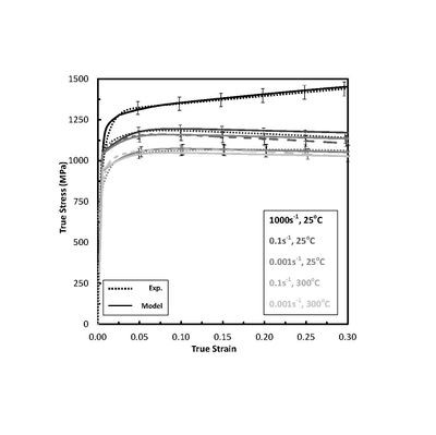
Tensile stress strain curves gathered from experiments and the calibrated response from the ISV/Damage model.
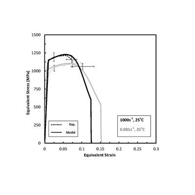
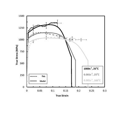
Torsion stress strain curves gathered from experiments and the calibrated response from the ISV/Damage model.
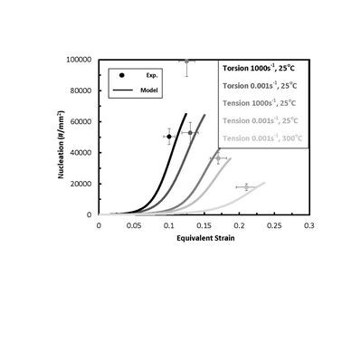
Comparison of the number density of voids, i.e. nucleation, on the fractured surface of the failed tension and torsion specimens and the model prediction of nucleation versus strain.
The nucleation at the failure strains shows good agreement, with the exception
of the high rate case, between experiments and the model predictions. The model
captures the stress state dependent trends which exhibit more nucleation of
voids in torsion than in tension for the experiments. Also, as temperature
increased, the nucleation decreased in both the experiments and the model.
While the model did show and increase in nucleation for the high rate tension
specimen, the model vastly under predicts the nucleation seen in the
experiment. However in torsion, the strain rate dependence on void size in the
experiments was not as strong as tension and therefore the model solution more
closely predicted the final nucleation.
With the initial and final damage quantified, and its evolution fitted to the
model, the plasticity parameters were then calibrated by comparison to the
stress strain curves gathered from the experiments. The compression
experimental results, shown in Figure 6, showed that for the low rate tests, no
hardening exists. In the high strain rate tests, however, work hardening does
exists revealing that the work hardening rate is a function of applied strain
rate. The overall yield strength of RHA also increases as strain rate increase.
The high temperature tests showed little effect on the hardening, but did
reduce the yield strength considerably. No failure was observed in the
compression experiments to 60% true strain. The model predictions show
excellent agreement with the compressive experimental data, as shown as the
solid curves in Figure 6.
Tension tests, shown in Figure 7, revealed similar strain rate dependence on
yielding as in compression. The high strain rate experimental oscillations were
assumed to be a result from the stress wave interaction with the bars and
specimen grips during experimentation and were not assumed to be a result from
material. The failure strain level for the room temperature low rate
experiments were less than that of the higher temperature tests which show that
damage is temperature dependent. The high strain rate experiment showed a
significant reduction in strain to failure as well. Because the nucleation at
high rate was not accurately captured, as shown previously in Figure 5, the
strain to failure is over predicted. The reduction in ductility from low strain
rates to high strain rates is known to be a cause of nucleation strain rate
dependence. A different method for introducing strain rate dependence in
nucleation would be necessary to capture the high nucleation seen in the
tension experiments. One way to capture nucleation more accurately, could be
performed by the addition of a power term to J2.. This would allow the
dependence on J2 to be scaled nonlinearly, rather than a simple direct
relationship as is used in this study.
The torsion experiments were all performed at room temperature. Figure 8 shows
the results which exhibited similar yield strength dependence on strain rate as
the tension and compression experiments. However, the hardening rate dependence
on strain rate was very low. The hardening rate for torsion was higher at the
low rate than for tension and compression, but is similar for the high rate
case. This shows that the hardening rate for RHA is stress state dependent. The
final strains for the torsion experiments were overpredicted in both
experiments, however, ABS can exist in high stain rate torsion tests and can
have an effect on the perceived strain to failure. However, the stress
strain response was captured relatively well for the torsion tests.
Acknowledgements
This work was performed at Mississippi State University's Center for Advanced Vehicular Systems(CAVS) and was funded by the US Army Engineer Research Development Center (ERDC) under Grant W912HZ-11-C-0021 from the Department of Homeland Security (DHS). The authors graciously thank Ric Cariño for assistance using the DMG fit software.
References
1. Whittington, W. R., Oppedal, A. L., Turnage, S., Hammi, Y., Rhee, H., Allison, P. G., ... & Horstemeyer, M. F. (2014). Capturing the effect of temperature, strain rate, and stress state on the plasticity and fracture of rolled homogeneous armor (RHA) steel. Materials Science and Engineering: A, 594, 82-88.