
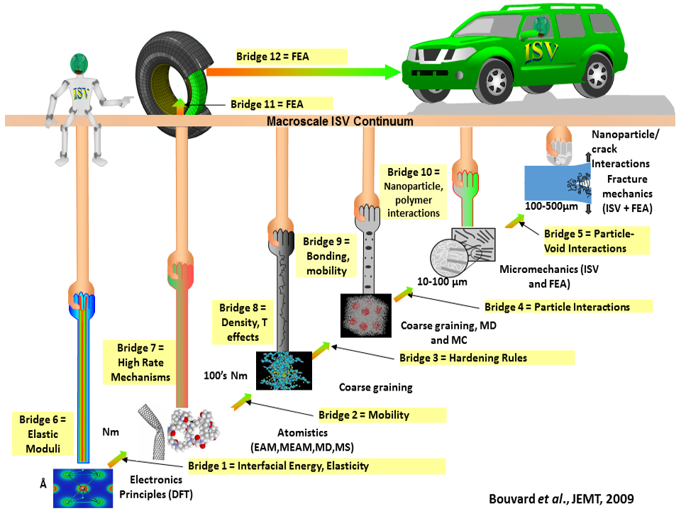
Materials Modeling and Simulation
In addition to hands-on material capabilities, CAVS' facilities also have equipment that allows CAVS researchers the ability to model a range of materials, including metals, polymers, bio-materials and cementitious materials. CAVS' design and optimization abilities allow our researchers to evaluate the materials while involved in a variety of tests, including fatigue and fracture, crashworthiness, corrosion and heat treatment, then to adjust the materials in order to reach prime material optimization.
Multiscale Modeling and Simulation
Metals
Multiscale modeling techniques employed at CAVS allow the simulation of materials, including novel metal alloys, from the scale of individual atoms and their electronic structure all the way to complete finished structure. To learn more, click the link below:
Polymers
CAVS researchers are exploring the use of polymers as a prime candidate for future engineering applications. Constructed of highly complex arrangements, polymers can lead the way to highly complex mechanical properties. Increased insight into polymer properties will lead to expansion of polymer usage in high stress and high impact situations.
By using Integrated Computational Materials Engineering (ICME) to study polymer properties, researchers can reduce the cost associated with other methods, while predicting mechanical behavior of polymers through material models and internal state variables (ISV). These variables can be found at the macroscale down to simulations performed at the atomic level.
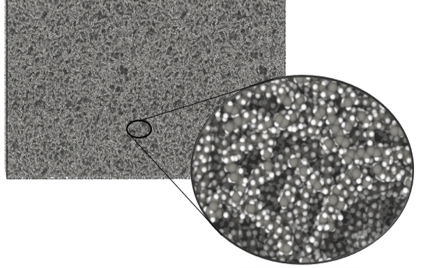
Areas of application for polymer modeling and simulation include organo-metallic interface study and reinforced polymeric material study.
Bio-Materials
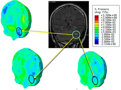
Researchers at the Center for Advanced Vehicular Systems conduct state-of-the-art traumatic brain injury (TBI) research, related to head injuries from contact sports, blast incidents and highway accidents. Our research efforts involve multiscale biomechanical experimentation and computational modeling that assists in TBI diagnostic techniques, injury biomechanics and human-centric engineering design. Additionally, our research also focuses on multiscale experimentation across diverse strain rates and stress states relevant to TBI, as well as on surrogate porcine tissues, in vivo neuron cell cultures and in vivo rodent models. The data obtained from biomechanical experiments feeds into a microstructure-based multiscale constitutive model for the brain to accurately capture primary and secondary injuries arising from TBI.
The complex nature of TBI necessitates that computational modeling also include nanoscale mechanical aspects. By performing molecular dynamics to simulate the membrane during injury scenarios, nanoscale mechanical and physiological damage can be elucidated and incorporated into the microstructure-based multiscale constitutive model for the brain.
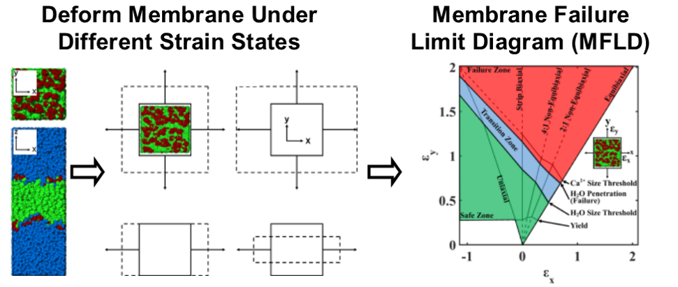
Strain State Deformation Simulation Overview And Membrane Failure Limit Diagram Result. Based on figures from Murphy, M.A. et al. 2018. “Molecular Dynamics Simulations Showing 1-Palmitoyl-2-Oleoyl-Phosphatidylcholine (POPC) Membrane Mechanoporation Damage under Different Strain Paths.” Journal of Biomolecular Structure and Dynamics.
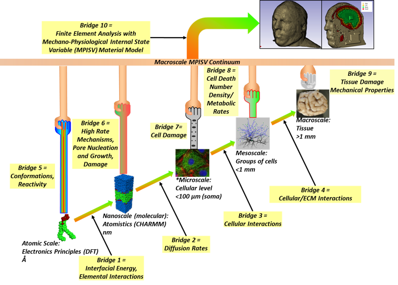
Multiscale Modelling Hierarchy for Traumatic Brain Injury. Modified from Murphy, Michael A. et al. 2016. “Nanomechanics of Phospholipid Bilayer Failure under Strip Biaxial Stretching Using Molecular Dynamics.” Modelling and Simulation in Materials Science and Engineering 24(5): 055008. http://stacks.iop.org/0965-0393/24/i=5/a=055008.
Cementitious Materials
CAVS’ modeling and simulation capabilities allow researchers to explore the capabilities of cementitious materials, examining specific properties, as well as impact responses. To learn more, click the link below:
Design and Optimization
Additive Manufacturing
Multiscale modeling techniques employed at CAVS allow the simulation of materials, including novel metal alloys, from the scale of individual atoms and their electronic structure all the way to complete finished structures. Everything from aircraft engine components to medical devices can be reproduced computationally, allowing for robust, inexpensive simulations for design and optimization of additively manufactured parts.
Fatigue and Fracture
Crack-Growth Based Fatigue Modeling
Researchers at CAVS have shown that fatigue-life prediction, based on the crack-growth approach, can be considered as an efficient and reliable method for materials fabricated via Additive Manufacturing (AM) process Additive Manufactured (AM) materials. Crack growth based modeling of fatigue appears to be a promising technique for analyzing the life of AM materials under cyclic loading, considering that the cracks already exist in the AM materials (i.e. process induced voids).
To perform fatigue-life calculations, effective stress intensity factor, ΔKeff, as a function of crack growth rate, da/dN, should be obtained from the large-crack data. The plasticity-induced crack-closure model, FASTRAN, is able to predict the fatigue lives based on the size and geometry of initial flaws, as well as the fracture mechanic properties of the material. The variation of fatigue lives with respect to the defect size and shape (i.e. aspect ratio) can also be evaluated by changing the geometry of initial flaw, based on the variations observed in characteristics of defects.
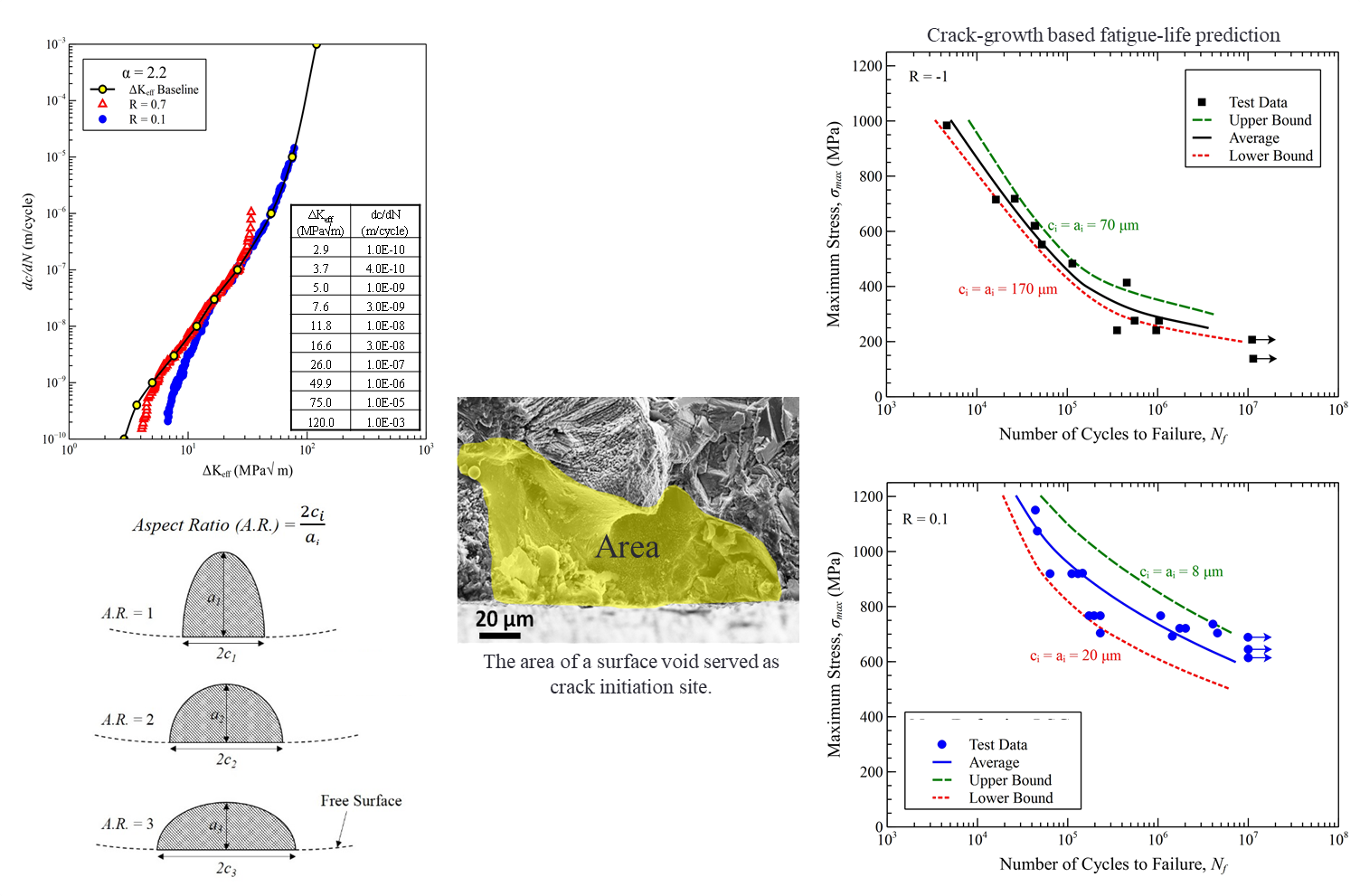
Figure 1. Experimental data and calculated fatigue curves for L-PBF Inconel 718 in using FASTRAN code.
Multistage Fatigue(MSF) Modeling
The multistage model was developed as a physically-based framework to evaluate sensitivity of fatigue response to various microstructural features. The MSF model also supports materials process design and component-specific tailoring of fatigue resistant materials.
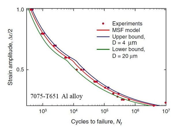
Figure 2. Predicted upper and lower bounds of total fatigue life for completely reversed, strain-controlled fatigue of 7075-T651 Al alloy (D: particle inclusion size).
MSF approach decomposes fatigue life into four consecutive stages (i.e. crack incubation, propagation of a microstructurally and physically small cracks, and long crack) based on the microstructural details of fatigue crack growth. In addition to the capability of predicting accurate upper and low bounds based on the defect size, this model can conceptually predict the variability due to grain size and orientation.
Powder Metallurgy
CAVS researchers have developed mathematical-based models for Powder Metallurgy manufacturing process, validating the compaction and sintering processes. To learn more, click the link below:
Crashworthiness
Finite Element Analysis
As tension between occupant safety during a crash and lightweight designs continues to be an important driver of modern vehicle designs, researchers at CAVS are investigating methods of safety optimization. While occupant safety may be defined and evaluated in various ways, maximizing energy absorption of structural components during impact has been adopted for vehicle designs by many manufacturers.
An alternative method to evaluate safety, but often not directly used in the design of structural components, is the use of a dummy model in the finite element (FE) simulation. This simulation estimates the forces and accelerations that would be experienced by a human in a crash environment.
- The energy absorption of collapsed components in the absence of a dummy
- An injury metric–based approach with the responses of the dummy as the bases
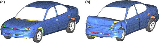
Full-scale finite element model of 1996 Dodge Neon (a)before impact; (b) 100ms after frontal impact.
Multi-objective optimization methods are used with finite element analysis (FEA) in the lightweight design for side-impact crashworthiness, considering the two different criterion. Results have shown that the optimum designs based on the two criteria are significantly different, and that the injury-based approach should be incorporated into vehicular lightweight design process when considering crashworthiness.
Multi-Objective Design Optimization
Because of the high computational cost of vehicle crash simulations, response surface methodology (RSM), which typically uses quadratic polynomials, is predominantly used for metamodeling in crashworthiness optimization.
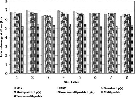
Research shows, however, that RSM may not be suitable for modeling highly nonlinear responses that can often be found in impact related problems, especially when using limited quantity of response samples. The radial basis functions (RBF) have been shown to be promising for highly nonlinear problems, but no application to crashworthiness problems has been found in the literature.
In a CAVS study, metamodels by RSM and RBF are used for multi-objective optimization of a vehicle body in frontal collision, with validations by finite element simulations using the full-scale vehicle model. The results show that RSM is able to produce good approximation models for energy absorption, and the model appropriateness can be well predicted by ANOVA (analysis of variance).
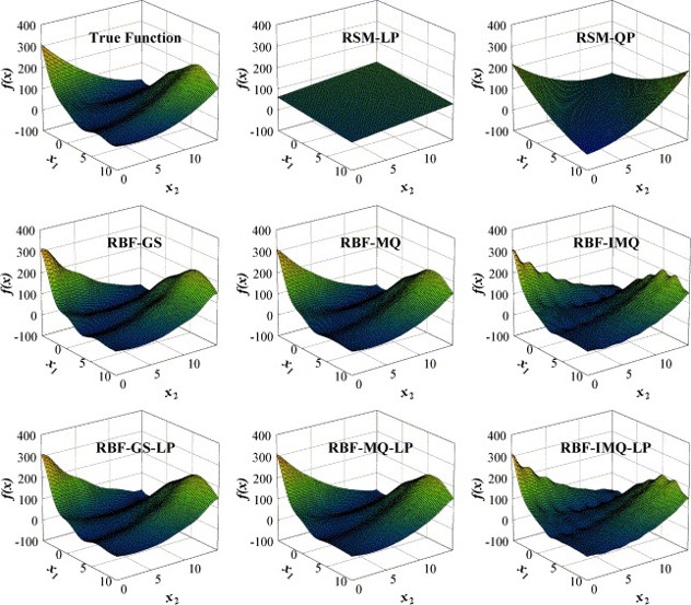
The Branin rcos function and the metamodels
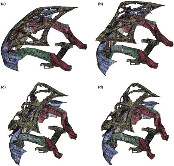
FE model of thirteen selected parts at (a) initial state, (b) 20 ms, (c) 40 ms, and (d) 100 ms after impact.
However, in the case of peak acceleration, RBF is found to generate better models than RSM based on the same number of response samples, with the multiquadric function identified to be the most stable RBF. Although RBF models are computationally more expensive, the optimization results of RBF models are found to be more accurate.
Hydroforming
Researchers at CAVS took a look at a hydroforming process through a parametric finite element analysis, using a history-dependent internal state variable model. Experiments were performed for the internal state variable model correlation and for validating a 2-in. copper tee hydroforming process simulation. Material model constants were determined from uniaxial stress–strain responses, which were obtained from tensile tests on the tube's material.
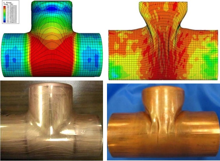
Comparison of the finite element simulation results with the experimental results from a well-processed hydroformed tee-tube and a processed hydroformed tee-tube that induced wrinkling.
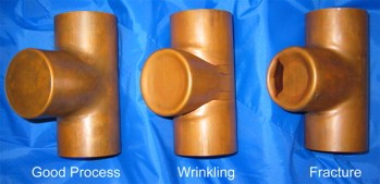
Comparison of a well-processed tee-tube, a wrinkled tee-tube, and a fractured tee-tube.
In the finite element simulations, the mesh and boundary conditions were integrated with the geometry and process parameters currently used in industry. The study resulted in key insights on the variation of different process parameters in relation to the finished product, including both velocity and pressure profiles, and bucking system characteristics.
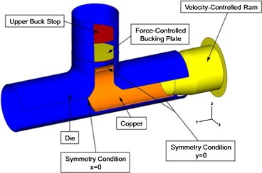
The finite element simulation set-up showing the different components of hydroforming process.
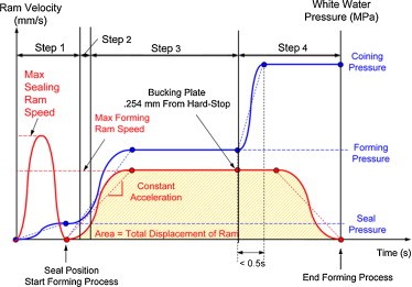
Simulation steps on pressure-time and velocity-time histories.
Integrated Computational Materials Engineering
ICME Community Resources
As an emerging discipline that is transforming materials science, ICME has the ability to accelerate materials development, integrate design and manufacturing, and unify these with the engineering design optimization process. It also efficiently employs greater accuracy in simulation-based design. To learn more, click the link below: